
F 250 4WD Super Duty V10-6.8L VIN Z CNG (2003)
^
Battery posts and cable clamps must be clean and tight for accurate meter indications.
^
Refer to the battery tester manual for complete directions for testing the charging system.
1. Turn off all lamps and electrical components.
2. Place the vehicle in transmission range NEUTRAL and apply the parking brake.
3. Carry out the Load Test and No-Load Test according to the following component tests:
Generator On-Vehicle Tests - Load Test
1. Switch the tester to the ammeter function.
2. Connect the positive and negative leads of the tester to the corresponding battery terminals.
3. Connect the current probe to the generator B+ output terminal, circuit 36 (YE/WH).
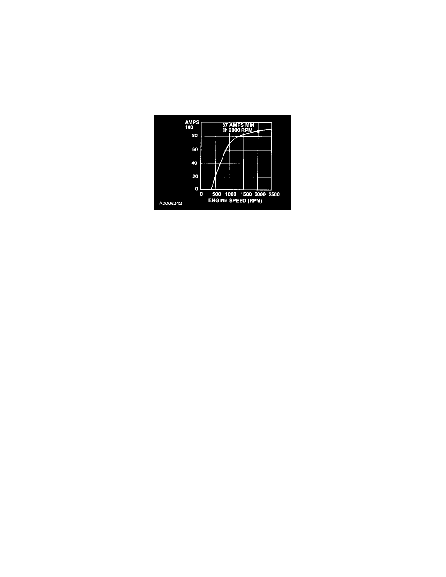
130 Amp Generator
4. With the engine running at 2,000 rpm, adjust the tester load bank to determine the output of the generator. Generator output should be at least 87
amps.
5. With the engine running, turn the A/C on, the blower motor on high speed and the headlamps on high beam.
6. Increase the engine speed to approximately 2,000 rpm. The voltage should increase a minimum of 0.5 volt above the base voltage.
^
If the voltage does not increase as specified, carry out the Generator On-Vehicle Tests.
^
If the voltage increases as specified, the charging system is operating normally.
Generator On-Vehicle Tests - No-Load Test
1. Switch the tester to the voltmeter function.
2. Connect the voltmeter positive lead to the generator B+ terminal and the negative lead to ground.
3. Turn all electrical accessories off.
4. With the engine running at 2,000 rpm, check the generator output voltage. The voltage should be between 13.0 and 15.0 volts. If not, refer to the
Symptom Chart. See: Testing and Inspection/With Single Generator/Diagnosis By Symptom