
F 350 2WD Pickup V8-460 7.5L VIN G EFI (1997)
black snap rings supplied in the kit.
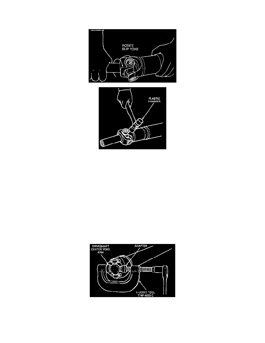
7. Install the remaining new bearing cups, spider, driveshaft slip yoke, driveshaft flange yoke and snap rings in the same manner.
8. Check U-joints for freedom of movement. The effort required for movement should not exceed 4 Nm (35 in lb) when measured with a spring
scale. If binding has resulted from misalignment during assembly, a sharp rap on the yokes with a brass or plastic hammer will seat bearing
needles. Take care to support the shaft end and do not strike the bearings during this procedure. Make sure U-joints rotate easily without binding
before installing driveshaft.
9. Lubricate the universal joints (if equipped with grease fittings) with Premium Long-Life Grease XG-1-C or -K or equivalent meeting Ford
specification ESA-M1C75-B.
Double Cardan Universal Joint
DISASSEMBLY
1. Place the driveshaft on a suitable workbench being careful not to damage the tube.
CAUTION: Under no circumstances is the driveshaft to be clamped in the jaws of a vise or similar holding fixture. Denting or localized fracture
of the tube can result, which can cause driveshaft failure during vehicle operation.
2. Mark the positions of the spiders, the driveshaft center yoke, and the driveshaft centering socket yoke as related to the stud yoke that is welded to
the front of the driveshaft.
3. Remove the snap rings that secure the bearings in the front of the driveshaft center yoke.
4. Position U-Joint Tool T74P-4635-C as shown. Tighten the tool clockwise until the bearing protrudes approximately 9.525 mm (3/8 inch) out of
the yoke.