
F 350 2WD Pickup V8-6.9L DSL (1983)
crankcase vent tube assembly consisted of a steel crankcase ventilation tube, a nylon backup ring and an O-ring, Figure 9. The new
crankcase vent tube assembly consists of a rubber crankcase ventilation hose, a nylon hose adapter and two (2) hose clamps, Figure 10.
ACTION:
If service is required, use the following procedure to install the crankcase vent tube assembly and crankcase depression regulator.
OLD DESIGN CRANKCASE VENT TUBE ASSEMBLY
1.
Refer to the Light Truck Shop Manual, Volume B, Section 22-08.
2.
Follow the instructions for removal and installation of the crankcase depression regulator (CDR).
NEW DESIGN CRANKCASE VENT TUBE ASSEMBLY
Removal and Inspection
1.
Remove the air cleaner and air cleaner housing from the intake manifold. Install the manifold protector cap (Tool No. T83T-9424-A) on the intake
manifold.
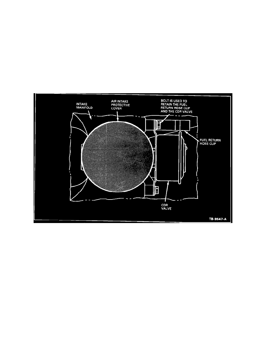
FIGURE 11
2.
Remove the two (2) bolts and washers which attach the CDR valve to the intake manifold.
NOTE:
ONE BOLT IS USED TO HOLD THE FUEL RETURN HOSE CLIP AND THE CDR VALVE, FIGURE 11. REMOVE THE FUEL
RETURN HOSE CLIP AND SET IT ASIDE DURING THE REMOVAL PROCESS.