
F 350 4WD Pickup V8-7.3L DSL Turbo VIN F (1994)
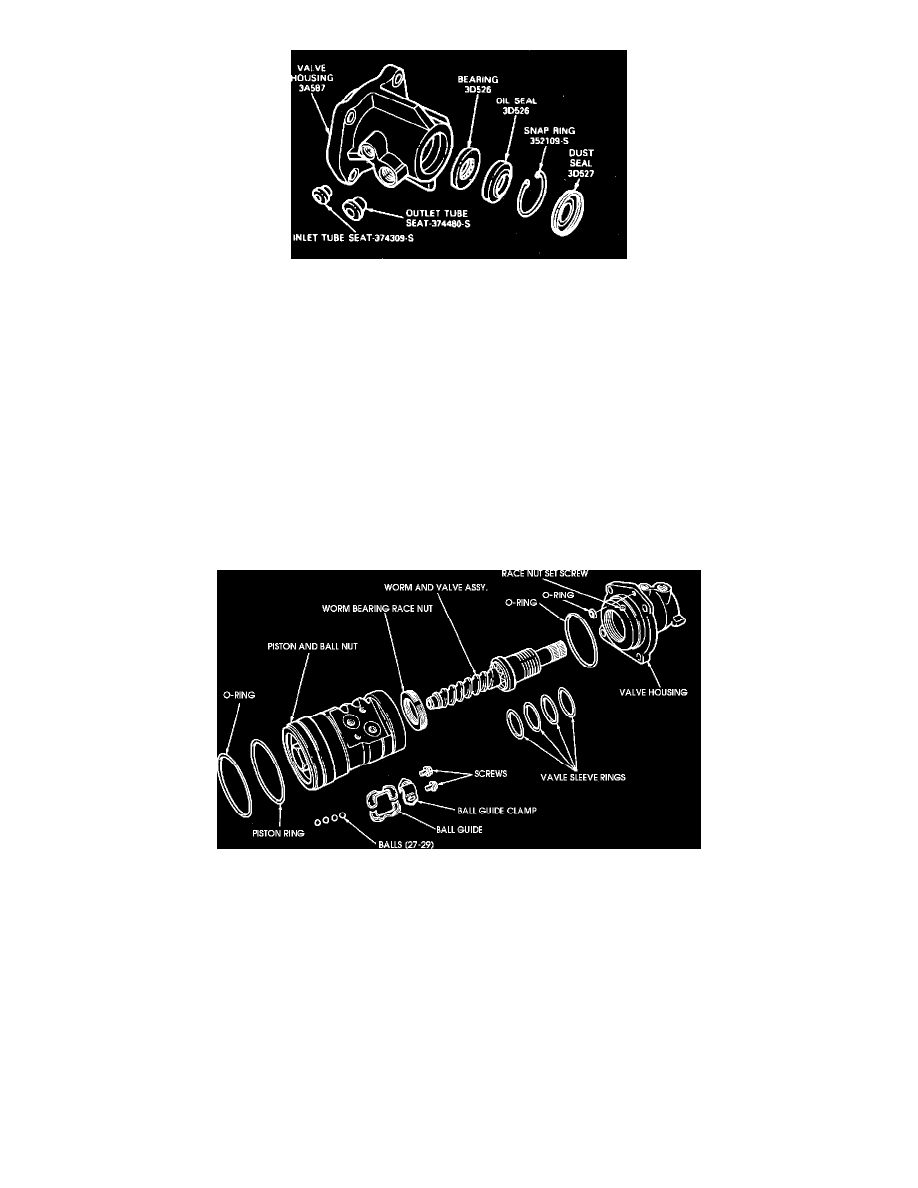
Fig. 4 Valve Housing
1. Remove dust seal and snap ring.
2. Invert housing and from opposite seal end, gently tap bearing and seal out of housing. Exercise care when inserting and removing tool to prevent
damage to valve bore in housing.
3. Remove oil inlet and outlet tube seats with "EZ-Out" if damaged.
4. Coat tube seats with petroleum jelly and position them in housing. Install and tighten tube nuts to press seats to proper location.
5. Coat bearing and seal surface in housing with a film of petroleum jelly.
6. Position bearing in valve housing. Seat bearing in housing with bearing installation tool No. T65P-3524-A1, or equivalent, ensuring that bearing
rotates freely.
7. Dip new oil seal in gear lube. Then position seal facing outward. Drive seal into housing until outer edge of seal does not quite clear snap ring.
8. Place snap ring in housing. Then drive on ring with bearing remover tool No. T65P-3524-A1, or equivalent, until snap ring seats in its groove to
locate seal properly.
9. Place dust seal in housing with dished side (rubber side) facing out. Drive dust seal in place so that it is located behind undercut in input shaft
when it is installed.
Worm & Valve Sleeve
Fig. 2 Ball And Nut Housing
1. Remove valve sleeve rings from sleeve by inserting blade of a small pocket knife carefully under them and cutting them off, without scratching
valve sleeve.
2. With worm end of the worm and valve sleeve assembly mounted into a soft jawed vise, install mandrel tool No. T75L-3517-A1, or equivalent,
over sleeve and slide one valve sleeve ring over tool.
3. Slide pusher tool No. T75L-3517-A2, or equivalent, over mandrel, then rapidly push down on pusher tool, forcing the ring down the ramp and into
the fourth groove of the valve sleeve. Repeat this step three more times, each time adding one of the spacer tools No. T75L-3517-A3, or
equivalent, under mandrel tool. Adding spacers each time will align mandrel tool with next groove of valve sleeve.
4. After installing all four valve sleeve rings, apply a light coat of gear lubricant to sleeve and rings.
5. Slowly install sizing tube tool No. T75L-3517-A4, or equivalent, over sleeve valve end of worm shaft and onto valve sleeve rings. Ensure rings
turn freely in grooves.