
F 350 4WD Pickup V8-7.3L DSL Turbo VIN F (1994)
lbs.).
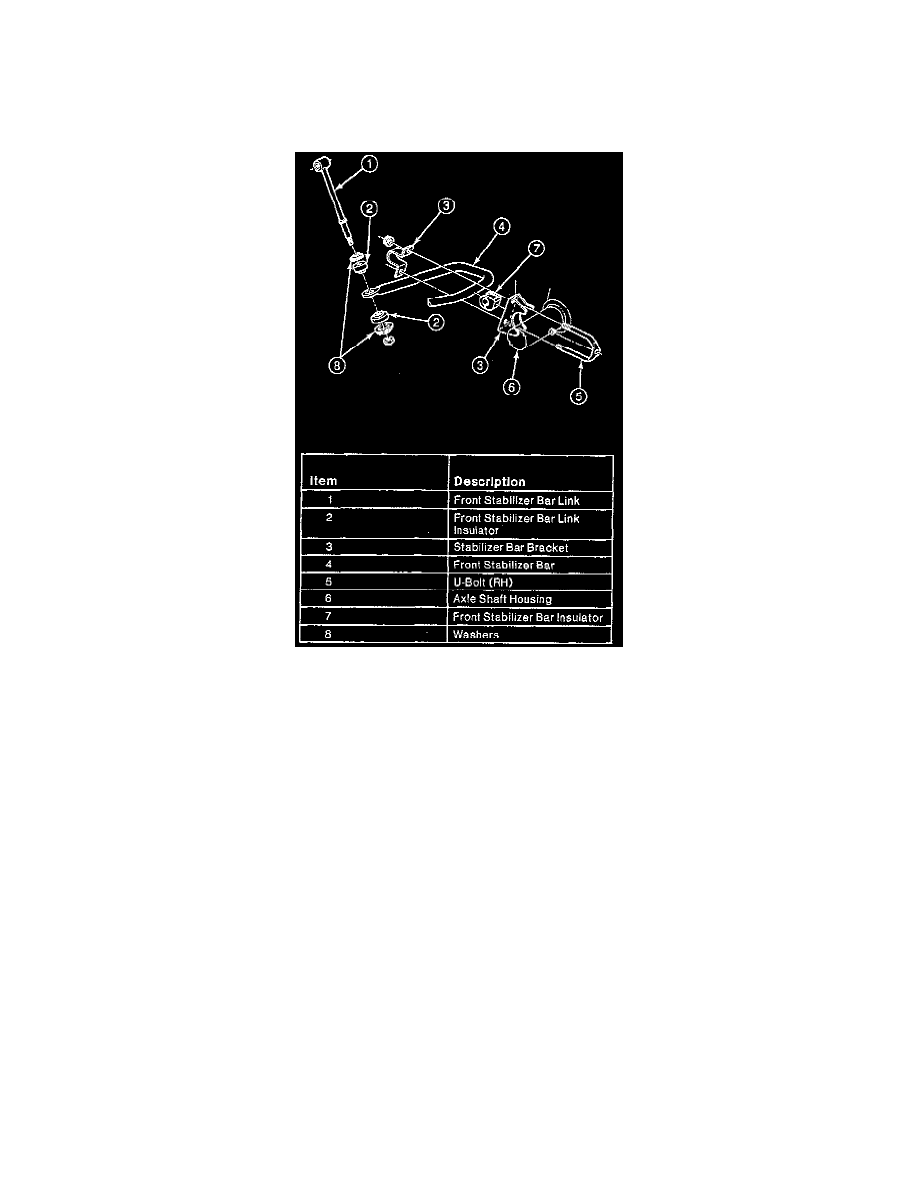
6. Connect the vent tube to the axle housing.
7. Connect the connecting rod and tie rod end to the steering knuckles. Secure the connecting rod end and tie rod end with castle nuts. Tighten to
70-100 Nm (52-74 ft. lbs.). Install cotter pins. If necessary, advance nut to next castellation to install cotter pin.
8. Connect front stabilizer bar link to front stabilizer bar. Tighten to 21-33 Nm ( 15-24 ft. lbs.).
9. If removed, position front stabilizer bar and stabilizer bar bracket on axle shaft housing, and tighten nuts to 48-68 Nm (35-50 ft. lbs.).
10. Install disc brake calipers and (part of front disc brake hub and rotor).
11. Install the wheels and tires on the vehicle.
12. Lower the vehicle to the ground.
Model 44-IFS
NOTE: When changing ratios on the front drive axle, it may be necessary to change the differential case along with the ring gear and drive pinion.
Ratios 2.72 to 1 up to 3.73 to 1 incorporate a thick differential case flange and a thin ring gear. Ratios 3.92 to 1 up to 4.09 to 1 incorporate a thin
differential case flange and a thick ring gear.
1. Remove axle assembly from vehicle, please refer to Transmission and Drivetrain/Drive Axles, Bearings and Joints/Axle Shaft Assembly/Axle
Shaft/Service and Repair/ See: Drive Axles, Bearings and Joints/Axle Shaft Assembly/Axle Shaft/Service and Repair
2. Loosen bolts retaining carrier to axle arm and drain fluid.
3. Remove right hand slip yoke and stub shaft.
4. Remove bolts attaching support arm to carrier, then the carrier assembly.