
F 350 4WD Pickup V8-7.3L DSL Turbo VIN F (1994)
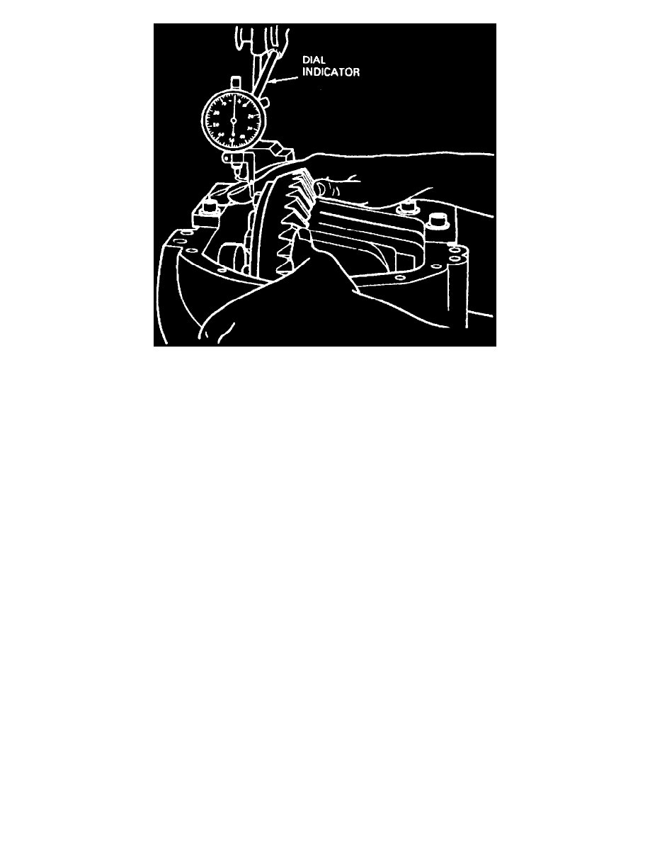
Fig. 6 Total Differential Case Endplay Inspection
3. Place differential case into carrier (without pinion). Differential case should move freely in carrier assembly. Position a suitable dial indicator
against differential case flanges. Locate tip of indicator on flat surface of one ring gear bolt. Force differential case toward dial indicator as far as
possible and zero dial indicator with force still applied. Dial indicator should have a minimum of 0.350 inch travel. Force differential case away
from dial indicator as far as it will go. Repeat this procedure until same reading is obtained. Record dial indicator reading as measurement "A" on
a work sheet for calculating ring gear backlash and differential bearing preload shims. This reading indicates amount of shims needed behind
differential side bearings to take up total clearance between differential bearing cup and carrier. This reading will be used during "Pinion & Ring
Gear Backlash Inspection".
4. Remove differential case from carrier. Do not remove differential case bearings at this time.
DRIVE PINION INSTALLATION
Two separate adjustments affect drive pinion and ring gear tooth contact: pinion depth and pinion to ring gear backlash.