
F 450 2WD Super Duty V10-6.8L VIN S (1999)
Inspection and Verification (Start Here)
1. Visually inspect for obvious signs of electrical damage. Refer to the following:
VISUAL INSPECTION
Electrical
-
Damaged wiring harness
-
Loose or corroded connectors
-
ABS Control Module
-
Generic Electronic Module or Central Timer Module (GEM/CTM)
-
Electronic Crash Sensor (ECS)
-
Overhead Trip Computer (OTC)
2. If the concern remains after inspection, connect the New Generation STAR (NGS) Tester to the Data Link Connector (DLC) located beneath the
instrument panel and select the vehicle to be tested from NGS Tester menu.
If NGS Tester does not communicate with the vehicle:
-
check that the program card is correctly installed.
-
check the connections to the vehicle.
-
check the ignition switch is in RUN position.
If the NGS Tester still will not communicate with the vehicle, refer to Information Bus (Multiplex Communication Network). See:
3. Refer to the Symptom Chart. See: Pinout Values and Diagnostic Parameters/Symptom Chart
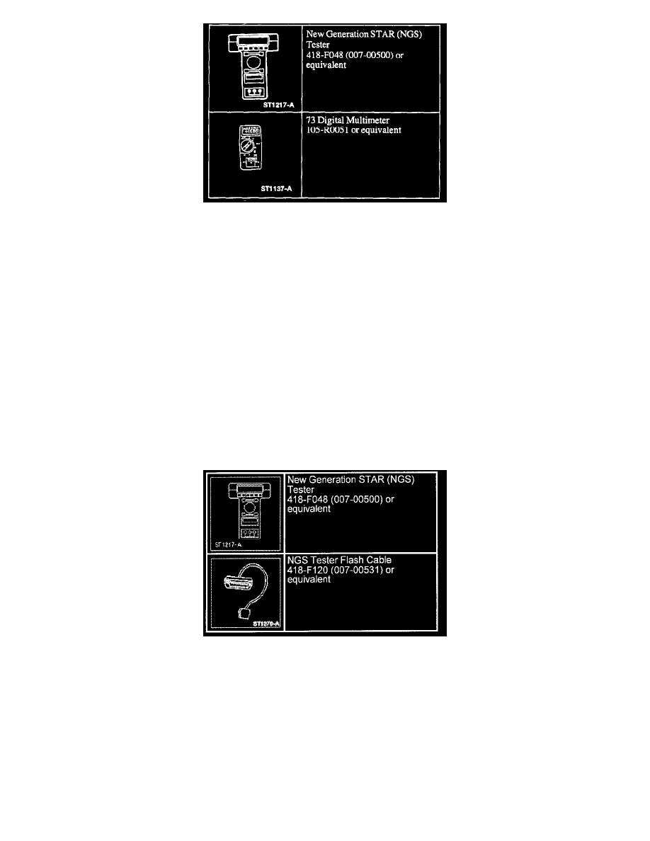
Special Tools