
F 450 2WD Super Duty V8-5.4L SOHC VIN L (2003)
Information Bus: Initial Inspection and Diagnostic Overview
Module Communications Network
INSPECTION AND VERIFICATION
1. Verify the customer concern.
2. Visually inspect for obvious signs of electrical damage:
VISUAL INSPECTION CHART
Electrical
-
Central junction box (CJB) fuse 12 (20A)
-
Wiring harness
-
Connectors
3. If the concern remains after the inspection, connect the diagnostic tool to the data link connector (DLC) located beneath the instrument panel and
select the vehicle to be tested from the diagnostic tool menu. If the diagnostic tool does not communicate with the vehicle:
-
check that the program card is correctly installed.
-
check the connections to the vehicle.
-
check the ignition switch position.
If the diagnostic tool still does not communicate with the vehicle, go to Pinpoint Test K. See: Pinpoint Tests/Test K
4. Go to Pinpoint Test PC. See: System Precheck
Visual Inspection
INSPECTION AND VERIFICATION
Visually inspect for obvious signs of electrical damage. Refer to visual inspection chart.
VISUAL INSPECTION CHART
- - Electrical - -
*
Wiring harness
*
Connectors
Configurable Modules
CONFIGURABLE MODULES
The vehicle contains the following modules that are configurable:
-
4-wheel anti-lock brake (4WABS) control module (if equipped)
-
vehicle security module
-
overhead trip computer (OTC) (if equipped)
-
restraint control module (RCM)
-
air suspension control module
-
4-wheel drive control module
-
instrument cluster
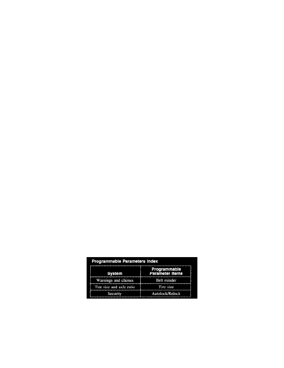
Programmable Parameters Index
System Precheck