
F 450 4WD Super Duty V10-6.8L (2009)
-
Are the resistances greater than 5,000 ohms?
Yes
CONNECT all modules. CONNECT the negative battery cable. GO to V34.
No
GO to V25.
-------------------------------------------------
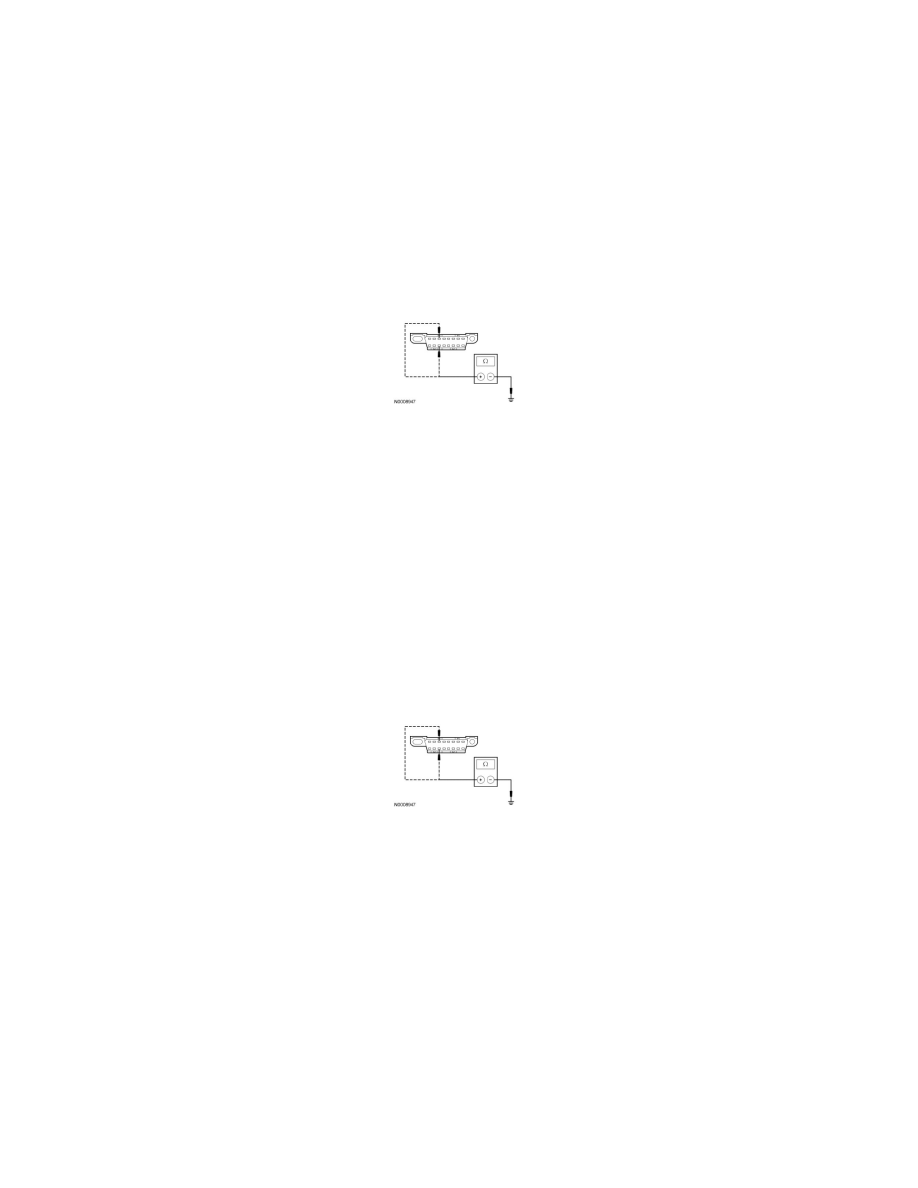
V25 CHECK THE MS-CAN (+) AND MS-CAN (-) CIRCUITS FOR A SHORT TO GROUND WITH THE ACM DISCONNECTED
-
Disconnect: ACM C240c.
-
Measure the resistance between the DLC C251-3, circuit VDB06 (GY/OG), harness side and ground; and between the DLC C251-11, circuit
VDB07 (VT/OG), harness side and ground.
-
Are the resistances greater than 5,000 ohms?
Yes
CONNECT all modules. CONNECT the negative battery cable. GO to V35.
No
If the vehicle is equipped with an APIM, GO to V26.
If the vehicle is not equipped with an APIM, GO to V27.
-------------------------------------------------
V26 CHECK THE MS-CAN (+) AND MS-CAN (-) CIRCUITS FOR A SHORT TO GROUND WITH THE APIM DISCONNECTED
-
Measure the resistance between the DLC C251-3, circuit VDB06 (GY/OG), harness side and ground; and between the DLC C251-11, circuit
VDB07 (VT/OG), harness side and ground.
-
Are the resistances greater than 5,000 ohms?
Yes
CONNECT all modules. CONNECT the negative battery cable. GO to V36.
No
GO to V27.
-------------------------------------------------
V27 CHECK THE MS-CAN (+) AND MS-CAN (-) CIRCUITS FOR A SHORT TO GROUND WITH THE IC DISCONNECTED
-
Disconnect: IC C220.
-
Measure the resistance between the DLC C251-3, circuit VDB06 (GY/OG), harness side and ground; and between the DLC C251-11, circuit
VDB07 (VT/OG), harness side and ground.