
F 550 2WD Super Duty V8-6.4L DSL Turbo (2008)
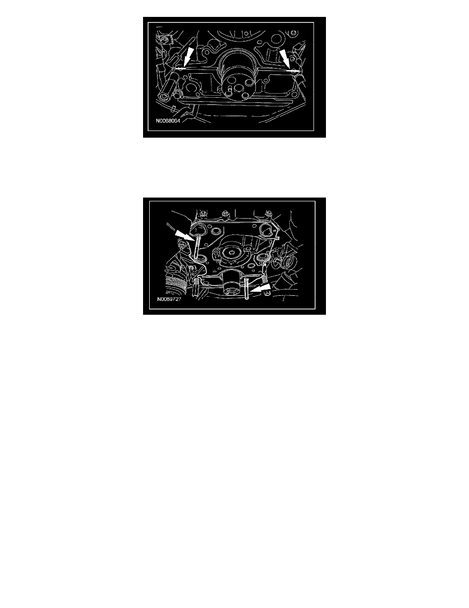
3. CAUTION: Failure to use guide pins to position the front cover gasket may lead to oil in the coolant.
NOTE: Use guide studs to aid in installation. Studs must be fabricated locally.
Position the front cover gasket on the engine and install guide pins.
4. Position the engine front cover and loosely install the bolts.
5. NOTE: Install oil pump drive rotors with marks pointing outward.
Lubricate the inner drive rotor with clean engine oil and install onto the crankshaft. Lubricate the outer drive rotor with clean engine oil and mesh
with the inner drive rotor.
6. Install a new press-in-place gasket, the oil pump housing and the 11 bolts.
^
Tighten the 7 long bolts to 31 Nm (23 lb-ft).
^
Tighten the 4 short bolts to 22 Nm (16 lb-ft).
7. Tighten the engine front cover bolts.
^
Tighten to 31 Nm (23 lb-ft).
8. NOTE: Install a new O-ring seal on the coolant pump.
If removed, install the coolant pump and the bolts.
^
Tighten to 31 Nm (23 lb-ft).
9. If removed, install the coolant pump pulley and the bolts.
^
Tighten to 31 Nm (23 lb-ft).
10. If removed, install a new press-in-place gasket. Install the thermostat housing, collar and bolts.
^
Tighten to 13 Nm (115 lb-inch).
11. CAUTION: Do not bend or flex the heater supply tube or damage to the tube may occur.
NOTE: Install a new O-ring seal.
Position back the heater supply tube.
12. Install the nut and bolts for the heater supply tube and engine wiring harness.
^
Tighten to 13 Nm (115 lb-inch).
13. Connect the ECT sensor electrical connector and wire retainer.