
F 550 4WD Super Duty V10-6.8L VIN S (2000)
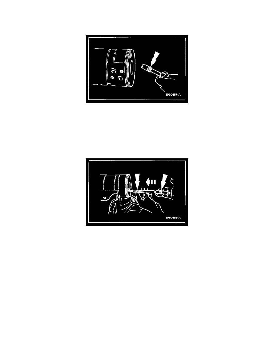
Press the adjuster seat into the sleeve using 2,224-11,120 N (500-2,500 lb) force until the shoulder on the seat bottoms against the sleeve and
remove the adjuster seat and sleeve assembly from the rack piston.
-
Repeat the procedure for the other poppet seat and sleeve assembly if removed.
3. CAUTION: Do not allow Loctite(R) or Locquic to get on the adjuster seat and sleeve assembly. The poppets will not function properly.
Carefully apply Locquic T primer to the threads in the poppet holes, and threads on the seat and sleeve assemblies. Allow to dry for ten minutes,
then carefully apply Loctite(R) RC680 to the same threads.
4. WARNING: Wear eye protection while assembling poppets, as spring-loaded poppets can eject and cause eye injury.
Place the rack piston in a soft-jawed vise and turn one poppet adjuster seat and sleeve assembly (slotted end out) into the poppet hole in one end of
the rack piston.
5. From the other end of the poppet hole in the rack piston, install the following:
-
one poppet
-
poppet spring
-
nylon spacer rod
-
push tube
-
other poppet
-
other poppet adjuster seat and sleeve assembly
6. Tighten both the poppet adjuster seat and sleeve assemblies to specification using Poppet Adjusting Seat Tool and a torque wrench.
Steering Gear Worm and Valve Sleeve - Motorhome
Steering Gear Worm and Valve Sleeve - Motorhome
Disassembly
NOTE: The following tools are available from Kent-Moore Tool Division, 29784 Little Mack, Roseville, MI 48066.
Adjuster Lock Nut Tool J37464, Adjuster Tool J37070, Bearing and Seal Tool J37071, Input Seal Installer J37073.