
F 550 4WD Super Duty V10-6.8L VIN S (2000)
13. Recheck the input shaft torque. It must match the torque measured in Step 11. Repeat Steps 11 and 12 if necessary.
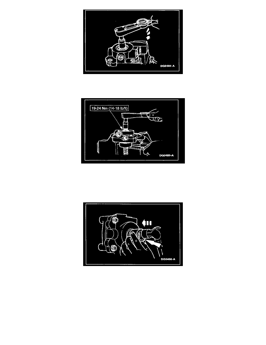
14. Stake the valve housing into the clockwise-most corner of two opposing slots in the locknut. Stake the locknut into the adjuster in two places (180
degrees apart) at the threaded area. Choose areas that have not been previously staked.
15. After staking, the torque required to rotate the input shaft must be greater than the torque noted in Step 11. The torque value must not exceed the
specified torque. Unstake and readjust if necessary.
16. Reposition the worm screw/valve housing subassembly in a soft-jawed vise, clamping tightly against the valve housing, so that the worm screw is
pointing sideways.
17. Apply clean grease to the outside and inside diameters (fill cavity between the lips) of the new input shaft seal and assemble it, garter spring side
first over the input shaft. Align the seal in the valve housing seal bore.
18. CAUTION: The input shaft seal must be square in the seal bore and installed to the correct depth.
Assemble Input Seal Installer Tool, small diameter end first, over the input shaft and against the seal and tap the tool until the tool shoulder is
squarely against the valve housing.
-
This will correctly position the seal in the housing bore just beyond the retaining ring groove.
19. Remove any seal material that may have sheared off and is in the seal bore and retaining ring groove.