
Festiva L4-81 1.3L SOHC EFI (1989)
fuel charging assembly cannot operate efficiently unless all other components in the system are performing correctly.
This group covers those tests and adjustment procedures related directly to carburetors and fuel injection. Other emission systems related to the fuel
system are covered in Group 55 of this manual. Refer to the diagnostic routines in Group 55 for the Diagnostics By Symptom menu.
1989
24-01-2
Fuel System Service
24-01-2
DESCRIPTION AND OPERATION (Continued)
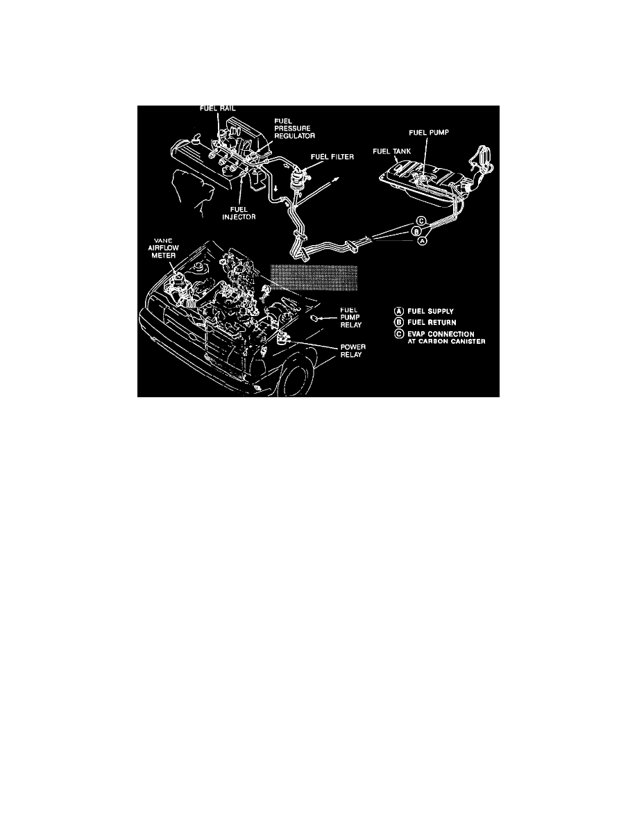
Electronic Fuel Injection The Electronic Fuel Injection system (EFI) meters fuel into the intake air stream through four injectors mounted on a tuned
intake manifold. The Electronic Control Assembly (ECA) accepts inputs from various engine sensors to compute the required fuel flow rate necessary to
maintain a prescribed air/fuel ratio throughout the entire engine operational range. The ECA then outputs a signal to the fuel injectors to meter the
required quantity of fuel. The system automatically senses fuel quantity requirements. It increases, decreases, or cuts-off fuel delivery to the engine based
on engine demands and driving conditions. The fuel delivery sub-system consists of a high pressure electrical fuel pump mounted in-tank, high pressure
fuel filter, fuel rail with pressure regulator, fuel injectors, fuel pump switch (in the
Vane Airflow Meter), fuel pump relay, fuel tank, inertia switch and connecting lines.
When the ignition is switched on, it turns the power relay on. The power relay provides power to the ECA, fuel pump relay, and fuel injectors. Power to
the fuel pump is supplied through the fuel pump relay. The inertia switch is a safety device used to shut off the fuel pump in the event of a collision. It is
connected between the fuel pump and the fuel pump relay. If the inertia switch is "tripped" it must be reset by depressing the button on top of the switch.
While cranking, fuel pump circuit ground is provided at the fuel pump relay to operate the fuel pump. After the engine starts, fuel pump circuit ground is
provided through the fuel pump switch located in the Vane Airflow Meter.
1989
24-05-8
Electronic Fuel Injection System
24-05-8