| Diagnosis and Testing Refer to Wiring Diagrams Section 303-06, for schematic and connector information. Worldwide Diagnostic System (WDS) Inspection and Verification - Verify the customer concern.
- Visually inspect for obvious signs of electrical damage.
Visual Inspection Chart | Electrical | | Fuse(s) | | Wiring harness | | Electrical connector(s) | | Relay | | Central junction box (CJB) | | Switch(es) | | Battery | | Starter motor | | Powertrain Control Module (PCM) | - If an obvious cause for an observed or reported concern is found, correct the cause (if possible) before proceeding to the next step.
- If the cause is not visually evident, verify the symptom and refer to the Symptom Chart.
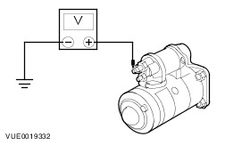
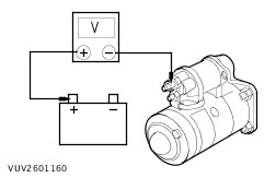
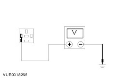
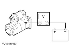
Symptom Chart | Symptom | Possible Sources | Action | | The engine does not crank/the relay does click | * Battery. | * REFER to: Charging System (414-00 Charging System - General Information, Diagnosis and Testing). | | * Starter motor. | * CARRY OUT the starter motor Component Test using WDS. | | * Relay. | * CARRY OUT the relay Component Test. REFER to the wiring diagrams. | | * Circuit(s). | * | | * PCM. | * REFER to WDS. | | The engine does not crank/the relay does not click | * Battery. | * REFER to: Charging System (414-00 Charging System - General Information, Diagnosis and Testing). | | * Fuse. | * INSTALL a new fuse as necessary. If the fuse fails again check for short to ground. | | * Passive anti-theft system (PATS). | * REFER to: Anti-Theft - Passive (419-01B Anti-Theft - Passive, Diagnosis and Testing). | | * Starter motor. | * CARRY OUT the starter motor Component Test using WDS. | | * Ignition switch. | * | | * Relay. | * CARRY OUT the relay Component Test. REFER to the wiring diagrams. | | * Circuit(s). | * | | The engine cranks slowly | * Battery. | * REFER to: Charging System (414-00 Charging System - General Information, Diagnosis and Testing). | | * Starter motor. | * CARRY OUT the starter motor Component Test using WDS. | | * Circuit(s). | * | | Unusual starter noise | * Starter motor. | * REMOVE the starter motor. REFER to: (303-06 Starting System) Starter Motor - 1.25L Duratec-16V (Sigma)/1.3L Duratec-8V (Rocam)/1.4L Duratec-16V (Sigma)/1.6L Duratec-16V (Sigma) (Removal and Installation), Starter Motor - 1.4L Duratorq-TDCi (DV) Diesel (Removal and Installation). INSPECT the starter motor gear for damage. INSTALL a new starter motor as necessary. | | * Flywheel ring gear. | * INSPECT the flywheel for damage. | | The starter spins but the engine does not crank | * Starter motor. | * REMOVE the starter motor.REFER to: (303-06 Starting System) Starter Motor - 1.25L Duratec-16V (Sigma)/1.3L Duratec-8V (Rocam)/1.4L Duratec-16V (Sigma)/1.6L Duratec-16V (Sigma) (Removal and Installation), Starter Motor - 1.4L Duratorq-TDCi (DV) Diesel (Removal and Installation). INSPECT the starter motor gear for damage. INSTALL a new starter motor as necessary. | | * Flywheel ring gear. | * INSPECT the flywheel for damage. | | The starter stops cranking the engine before the engine starts | * PCM. | * REFER to WDS. | Pinpoint Tests NOTE:Use a digital multimeter for all electrical measurements. | PINPOINT TEST A : THE ENGINE DOES NOT CRANK/THE RELAY DOES CLICK | | TEST CONDITIONS | DETAILS/RESULTS/ACTIONS | | A1: CHECK VOLTAGE TO STARTER SOLENOID | | | 1 Ignition switch in position III. | | | 2 Measure the voltage between starter motor terminal 50, harness side and ground. | | | Is the voltage greater than 10 volts? Yes No | | A2: CHECK THE VOLTAGE DROP | | | 1 Measure the voltage between starter motor terminal 30, component side and the battery positive terminal. | | | Is the voltage less than 0.5 volts? Yes No CLEAN and TIGHTEN all battery positive cable connections. TEST the system for normal operation. If the concern persists, INSTALL a new battery starter motor solenoid cable.
REFER to: Battery to Starter Motor Solenoid Cable - 1.3L Duratec-8V (Rocam) (414-01 Battery, Mounting and Cables, Removal and Installation) /
Battery to Starter Motor Solenoid Cable - 1.25L Duratec-16V (Sigma)/1.4L Duratec-16V (Sigma)/1.6L Duratec-16V (Sigma) (414-01 Battery, Mounting and Cables, Removal and Installation).
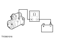
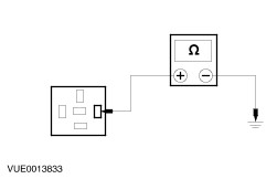
TEST the system for normal operation. | | A3: CHECK CIRCUIT 29-BB17 (OG/BK) FOR OPEN | | | 1 Ignition switch in position 0. | | | 2 Disconnect Starter Relay C423. | | | 3 Measure the voltage between starter relay C423 pin 3, circuit 29-BB17 (OG/BK), harness side and ground. | | | Is the voltage greater than 10 volts? Yes REPAIR circuit 50-BB10 (GY/BK). TEST the system for normal operation. No REPAIR circuit 29-BB17 (OG/BK). TEST the system for normal operation. | | A4: CHECK THE STARTER MOTOR GROUND CIRCUIT FOR OPEN | | | 1 Measure the resistance between the starter motor casing and battery ground terminal. | | | Is the resistance less than 0.5 ohms? Yes INSTALL a new starter motor.
REFER to: Starter Motor - 1.25L Duratec-16V (Sigma)/1.3L Duratec-8V (Rocam)/1.4L Duratec-16V (Sigma)/1.6L Duratec-16V (Sigma) (303-06 Starting System, Removal and Installation) /
Starter Motor - 1.4L Duratorq-TDCi (DV) Diesel (303-06 Starting System, Removal and Installation).
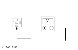
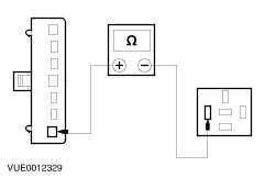
INSPECT the starter motor gear for damage. INSTALL a new starter motor as necessary. No CLEAN and TIGHTEN all battery and engine ground cable connections. TEST the system for normal operation. | | PINPOINT TEST B : THE ENGINE DOES NOT CRANK/RELAY DOES NOT CLICK | | TEST CONDITIONS | DETAILS/RESULTS/ACTIONS | | B1: CHECK THE SWITCHED POWER TO THE STARTER RELAY | | | 1 Disconnect Starter Relay C423. | | | 2 Ignition switch in position III. | | | 3 Measure the voltage between the starter motor relay C423 pin 1, harness side and ground. | | | Is the voltage greater than 10 volts? Yes No | | B2: CHECK CIRCUIT 50-BB16 (GY/BK) FOR OPEN | | | 1 Ignition switch in position 0. | | | 2 Disconnect Ignition Switch C329. | | | 3 Measure the resistance between the ignition switch C329 pin 7, circuit 50-BB16 (GY/BK), harness side and the starter relay C423 pin 1, circuit 50-BB16 (GY/BK), harness side. | | | Is the resistance less than 5 ohms? Yes INSTALL a new ignition switch.
REFER to: Ignition Switch (211-05 Steering Column Switches, Removal and Installation).
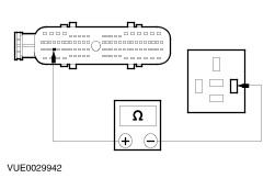
TEST the system for normal operation. No REPAIR the circuit. TEST the system for normal operation. | | B3: CHECK CIRCUIT 91S-BB16 (BK/RD) FOR OPEN | | | 1 Ignition switch in position II. | | | 2 Measure the resistance between the starter relay C423 pin 2, circuit 91S-BB16 (BK/RD), harness side and ground. | | | Is the resistance less than 5 ohms? Yes INSTALL a new starter relay. TEST the system for normal operation. No All except vehicles with diesel engine, GO to B4. Vehicles with diesel engine, GO to B5. | | B4: CHECK CIRCUIT 91S-BB16 (BK/RD) FOR OPEN | | | 1 Ignition switch in position 0. | | | 2 Disconnect PCM C343. | | | 3 Measure the resistance between the starter relay C423 pin 2, circuit 91S-BB16 (BK/RD), harness side and PCM C343 pin F30, 91S-BB16 (BK/RD), harness side. | | | Is the resistance less than 5 ohms? Yes CHECK the PATS system. REFER to WDS. No REPAIR the circuit. TEST the system for normal operation. | | B5: CHECK CIRCUIT 91S-BB16 (BK/RD) FOR OPEN | | | 1 Ignition switch in position 0. | | | 2 Disconnect PCM C372. | | | 3 Measure the resistance between the starter relay C423 pin 2, circuit 91S-BB16 (BK/RD), harness side and the PCM C372 pin C3, 91S-BB16 (BK/RD), harness side. | | | Is the resistance less than 5 ohms? Yes CHECK the PATS system. REFER to WDS. No Repair the circuit. Test the system for normal operation. | | PINPOINT TEST C : THE ENGINE CRANKS SLOWLY | | TEST CONDITIONS | DETAILS/RESULTS/ACTIONS | | C1: CHECK FOR VOLTAGE DROP | | | 1 Ignition switch in position III. | | | 2 Measure the voltage between the starter motor terminal 30, component side and the battery positive terminal. | | | Is the voltage less than 0.5 volts? Yes No CLEAN and TIGHTEN all battery positive cable connections. TEST the system for normal operation. If the concern persists, INSTALL a new battery to starter motor solenoid cable.
REFER to: Battery to Starter Motor Solenoid Cable - 1.3L Duratec-8V (Rocam) (414-01 Battery, Mounting and Cables, Removal and Installation) /
Battery to Starter Motor Solenoid Cable - 1.25L Duratec-16V (Sigma)/1.4L Duratec-16V (Sigma)/1.6L Duratec-16V (Sigma) (414-01 Battery, Mounting and Cables, Removal and Installation).
Test the system for normal operation. | | C2: CHECK FOR GROUND CONNECTION | | | 1 Ignition switch in position III. | | | 2 Measure the voltage between the starter motor case and the battery ground terminal. | | | Is the voltage less than 0.5 volts? Yes CHECK the battery.
REFER to: Charging System (414-00 Charging System - General Information, Diagnosis and Testing).
TEST the system for normal operation. No CLEAN and TIGHTEN all battery ground cable connections, starter motor mounting and body to ground straps. TEST the system for normal operation. If the concern persists, INSTALL a new battery ground cable. Test the system for normal operation. | |