4
-
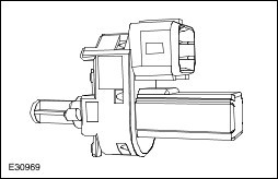
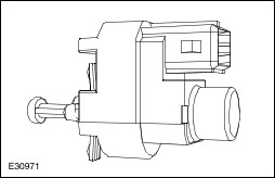
Throttle flap return spring
5
-
Intermediate shaft with gear
6
-
Electric motor with pinion
The APP sensor sends the data containing the driver's acceleration requirement to the PCM. This information depends directly on the movement of the accelerator pedal.
The PCM processes this information and converts it into an output signal for the throttle control unit (TCU). This output signal is the control for the electric motor.
The electric motor moves the throttle flap spindle by means of the gear set.
The throttle flap position is adjusted and monitored in a closed control loop. The TP sensor provides the PCM with the information on the actual position of the throttle flap.
Standby function
If a fault develops in the throttle control unit (TCU), a standby function is carried out. This standby function allows a slight opening of the throttle flap, so that enough air passes through to allow limited engine operation.
For this purpose, there is an throttle flap adjustment screw on the throttle housing. The return spring closes the throttle flap until the stop of the toothed segment touches the stop screw. In this way a defined throttle flap gap is formed for limp home mode.
The stop screw has a spring loaded pin, which holds the throttle flap open for limp home mode. In normal operating mode, this spring loaded pin is pushed in by the force of the electric motor when the throttle flap must be closed past the limp home position (e.g. for idle speed control or overrun shutoff).
CPP switch
The CPP switch is located directly on the pedal box.
The engine management recognises gearshifts through the CPP switch and thus improves engine running characteristics.
The CPP switch passes a ground signal to the PCM when the clutch pedal is depressed (disengaged).
(Brake Pedal Position) BPP switch
There are two brake pedal switches at the pedal box: the brake lamp switch and the BPP switch. The brake lamp switch only serves to switch on the brake lamps. The BPP switch is used for engine management purposes.
The BPP switch provides the PCM with the information that the vehicle will be decelerated.
The BPP switch is closed in the rest state (brake pedal not depressed) and sends a ground signal to the PCM.
If when the APP sensor has failed, the BPP is operated, the engine will be controlled to run at idle speed by the PCM.
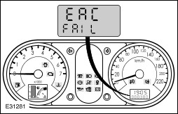
APP sensor
If a fault occurs in the APP sensor or the throttle control unit (TCU) during vehicle operation, then this will be briefly indicated by a digital display in the instrument cluster after the ignition is switched on, and a trouble code will be stored in the PCM.
If one potentiometer fails, the engine will run with reduced power (maximum torque 80 Nm), if both potentiometers fail, the engine will run with reduced power (maximum torque 55 Nm).
This warning may also be indicated if the engine does not start. The cause may be a poor state of charge of the battery.
The warning indication normally disappears once the battery is re-charged.