| Removal and Installation Special Tool(s) | | Remover, quick-release coupling 1/2" (blue) 412-027 (34-001) | | | Remover, quick-release coupling 5/8" (black) 412-038 (34-003) | Removal All vehicles | | -
Drain the cooling system. For additional information, refer to: Cooling System Draining, Filling and Bleeding - 1.25L Duratec-16V (Sigma)/1.3L Duratec-8V (Rocam)/1.4L Duratec-16V (Sigma)/1.6L Duratec-16V (Sigma) (303-03A Engine Cooling - 1.25L Duratec-16V (Sigma)/1.3L Duratec-8V (Rocam)/1.4L Duratec-16V (Sigma)/1.6L Duratec-16V (Sigma), General Procedures), Cooling System Draining, Filling and Bleeding - 1.25L Duratec-16V (Sigma)/1.3L Duratec-8V (Rocam)/1.4L Duratec-16V (Sigma)/1.6L Duratec-16V (Sigma) (303-03A Engine Cooling - 1.25L Duratec-16V (Sigma)/1.3L Duratec-8V (Rocam)/1.4L Duratec-16V (Sigma)/1.6L Duratec-16V (Sigma), General Procedures), Cooling System Draining, Filling and Bleeding (303-03C Engine Cooling - 2.0L Duratec-HE (MI4), General Procedures), Cooling System Draining, Filling and Bleeding (303-03D Engine Cooling - 1.6L Duratorq-TDCi (DV) Diesel, General Procedures). | | | -
Remove the right-hand headlamp assembly.
For additional information, refer to: Headlamp Assembly (417-01 Exterior Lighting, Removal and Installation).
| | | -
Drain the air conditioning system.
For additional information, refer to: Air Conditioning (A/C) System Recovery, Evacuation and Charging (412-00 Climate Control System - General Information, General Procedures).
| | | -
Remove the instrument panel.
For additional information, refer to: Instrument Panel (501-12 Instrument Panel and Console, Removal and Installation).
| | | -
Remove the air cleaner. For additional information, refer to: (303-12 Intake Air Distribution and Filtering) Air Cleaner - 1.25L Duratec-16V (Sigma)/1.4L Duratec-16V (Sigma)/1.6L Duratec-16V (Sigma) (Removal and Installation), Air Cleaner - 1.4L Duratorq-TDCi (DV) Diesel (Removal and Installation), Air Cleaner - 2.0L Duratec-HE (MI4) (Removal and Installation), Air Cleaner - 1.6L Duratorq-TDCi (DV) Diesel (Removal and Installation). | | | -
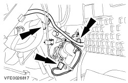
Detach the coolant hoses from the heater core. | | | -
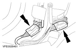
Remove the retaining clips of the quick-release couplings on the refrigerant lines. | | | -
Using the special tool, detach the left-hand refrigerant line from the evaporator core. - Discard the O-ring seals.
| | | -
Using the special tool, detach the right-hand refrigerant line from the evaporator core. - Discard the O-ring seals.
| | | -
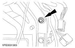
Unscrew and remove the nut from the heater core and evaporator core housing. | | | -
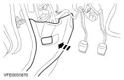
Unclip part of the left-hand footwell trim. | | | -
Disconnect the left-hand electrical connector of the instrument panel wiring harness (the footwell trim is shown removed for clarity). | | | -
Remove the ground strap bolt in the left-hand footwell. | | | -
Disconnect the electrical connector of the generic electronic module (GEM). | | | -
Detach the GEM from the in-vehicle crossbeam and lay it to one side. | | | -
Unclip part of the right-hand footwell trim. | | | -
Disconnect the right-hand electrical connector of the instrument panel wiring harness (the footwell trim is shown removed for clarity). | | | -
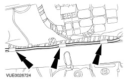
Detach the antenna cable from the right-hand upper clip on the in-vehicle crossbeam. | | | -
Detach the antenna cable from the right-hand lower clips on the in-vehicle crossbeam. | | | -
Detach the antenna cable from the central clips on the in-vehicle crossbeam. | Vehicles with electronic automatic temperature control (EATC) | | -
Disconnect the electrical connectors for the footwell vent/duct blend door actuator and the temperature blend door actuator. | All vehicles | | -
Disconnect the electrical connectors for the blower motor, blower motor resistor and air inlet blend door actuator. | | | -
Disconnect the electrical connector from the airbag module. - Unclip the wiring harness.
| | | -
Unscrew and remove the ground cable bolt from the airbag module. | | | -
Disconnect the electrical connector of the handbrake warning lamp switch. | | | -
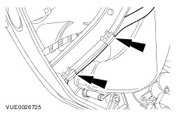
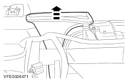
Remove the bolts of the windshield air duct (left-hand side shown). | | | -
Remove the windshield air ducts (left-hand side shown). | | | -
Mark the position of the in-vehicle crossbeam relative to the A-pillars (left-hand side shown). | | | -
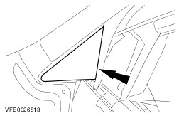
Remove the A-pillar outer trims (left-hand side shown). | | | -
Remove the caps (left side shown). | | | -
Remove the in-vehicle crossbeam side bolts. | | | -
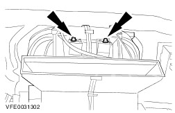
Remove the upper bolts of the heater core and evaporator core housing. | | | -
Remove the side bolts from the heater core and evaporator core housing (left side shown). | | | -
Remove the in-vehicle crossbeam lower bolts. | | | -
Remove the in-vehicle crossbeam upper bolts. | | | -
Remove the in-vehicle crossbeam. - Lift the in-vehicle crossbeam.
- Pull the in-vehicle crossbeam rearwards.
| | | -
WARNING:Before performing any work on the electrical booster heater, make certain that the surface of its heating element has cooled to ambient temperature. Failure to observe this instruction can lead to injury. Detach the electrical booster heater from the heater core and evaporator core housing and lay it to one side (if equipped). | | | -
CAUTION:Make sure that the water drain tube is not damaged when laying down the housing. Remove the heater core and evaporator core housing. | Installation All vehicles | | -
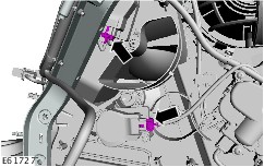
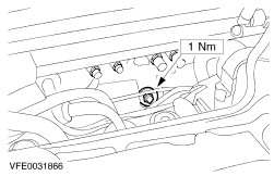
CAUTION:Ensure that the adjustment nut for the heater core and evaporator core housing is freely accessible. Screw on the adjustment nut for the heater core and evaporator core housing (the heater core and evaporator core housing seal is shown removed for clarity). - Tighten the adjustment nut to the stop.
- Undo the adjustment nut one turn.
| | | -
CAUTION:Make certain that the rubber grommet of the heater core and evaporator core housing water drain tube is correctly located in the vehicle floor. Install the heater core and evaporator core housing. | | | -
CAUTION:Ensure that the rubber grommet for the wiring harness of the electrical additional heater is correctly located in the bulkhead. Attach the electrical additional heater to the heater core and evaporator core housing (if equipped). | | | -
Install the in-vehicle crossbeam. - Slide the in-vehicle crossbeam forwards.
- Lower the in-vehicle crossbeam.
| | | -
Align the in-vehicle crossbeam to the A-pillars (left-hand side shown). | | | -
Install the upper bolts on the in-vehicle crossbeam. | | | -
Install the lower bolts on the in-vehicle crossbeam. | | | -
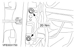
Install the side bolts on the heater core and evaporator core housing (left-hand side shown). | | | -
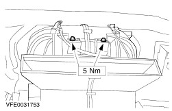
Install the upper bolts on the heater core and evaporator core housing. | | | -
Install the side bolts on the in-vehicle crossbeam. | | | -
Install the caps (left-hand side shown). | | | -
Install the outer A-pillar trims (left-hand side shown). | | | -
Install the windshield air ducts (left-hand side shown). | | | -
Install the bolts of the windshield air ducts (left-hand side shown). | | | -
Connect the electrical connector of the handbrake warning lamp switch. | | | -
Install the ground cable bolt for the airbag module. | | | -
Connect the airbag module connector. - Clip the wiring harness in place.
| | | -
Connect the electrical connectors for the blower motor, the blower motor resistor and the air inlet blend door actuator. | Vehicles with electronic automatic temperature control (EATC) | | -
Connect the electrical connectors for the footwell vent/duct blend door actuator and the temperature blend door actuator. | All vehicles | | -
Attach the antenna cable to the middle clips on the in-vehicle crossbeam. | | | -
Attach the antenna cable to the right-hand lower clips on the in-vehicle crossbeam. | | | -
Attach the antenna cable to the right-hand upper clip on the in-vehicle crossbeam. | | | -
Connect the right-hand electrical connector of the instrument panel wiring harness (the footwell trim is shown removed for clarity). | | | -
Clip the right-hand footwell trim in place. | | | -
Attach the GEM to the in-vehicle crossbeam. | | | -
Connect the GEM electrical connector. | | | -
Install the left-hand footwell ground cable bolt. | | | -
Connect the left-hand electrical connector of the instrument panel wiring harness (the footwell trim is shown removed for clarity). | | | -
Clip the left-hand footwell trim in place. | | | -
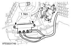
Install the nut on the heater core and evaporator core housing. | | | -
NOTE:Lubricate the refrigerant line O-ring seals with clean refrigerant oil before installation. Connect the right-hand refrigerant line to the evaporator core. - Install new refrigerant line O-ring seals.
| | | -
NOTE:Lubricate the refrigerant line O-ring seals with clean refrigerant oil before installation. Connect the left-hand refrigerant line to the evaporator core. - Install new refrigerant line O-ring seals.
| | | -
Install the retaining clips on the quick-release couplings on the refrigerant lines. | | | -
Attach the coolant hoses to the heater core. | | | -
Install the air cleaner. For additional information, refer to: (303-12 Intake Air Distribution and Filtering) Air Cleaner - 1.25L Duratec-16V (Sigma)/1.4L Duratec-16V (Sigma)/1.6L Duratec-16V (Sigma) (Removal and Installation), Air Cleaner - 1.4L Duratorq-TDCi (DV) Diesel (Removal and Installation), Air Cleaner - 2.0L Duratec-HE (MI4) (Removal and Installation), Air Cleaner - 1.6L Duratorq-TDCi (DV) Diesel (Removal and Installation). | | | -
Install the instrument panel.
For additional information, refer to: Instrument Panel (501-12 Instrument Panel and Console, Removal and Installation).
| | | -
Fill the air conditioning system.
For additional information, refer to: Air Conditioning (A/C) System Recovery, Evacuation and Charging (412-00 Climate Control System - General Information, General Procedures).
| | | -
Install the right-hand headlamp assembly.
For additional information, refer to: Headlamp Assembly (417-01 Exterior Lighting, Removal and Installation).
| | | -
Fill and bleed the cooling system. For additional information, refer to: Cooling System Draining, Filling and Bleeding - 1.25L Duratec-16V (Sigma)/1.3L Duratec-8V (Rocam)/1.4L Duratec-16V (Sigma)/1.6L Duratec-16V (Sigma) (303-03A Engine Cooling - 1.25L Duratec-16V (Sigma)/1.3L Duratec-8V (Rocam)/1.4L Duratec-16V (Sigma)/1.6L Duratec-16V (Sigma), General Procedures), Cooling System Draining, Filling and Bleeding - 1.25L Duratec-16V (Sigma)/1.3L Duratec-8V (Rocam)/1.4L Duratec-16V (Sigma)/1.6L Duratec-16V (Sigma) (303-03A Engine Cooling - 1.25L Duratec-16V (Sigma)/1.3L Duratec-8V (Rocam)/1.4L Duratec-16V (Sigma)/1.6L Duratec-16V (Sigma), General Procedures), Cooling System Draining, Filling and Bleeding (303-03C Engine Cooling - 2.0L Duratec-HE (MI4), General Procedures), Cooling System Draining, Filling and Bleeding (303-03D Engine Cooling - 1.6L Duratorq-TDCi (DV) Diesel, General Procedures). | |