| Diagnosis and Testing Refer to Wiring Diagrams Section 413-00, for schematic and connector information. Inspection and Verification - Verify the customer concern.
- Visually inspect for obvious signs of electrical damage.
Visual Inspection Chart | Electrical | | Fuse(s) | | Wiring harness | | Electrical connector(s) | | Light emitting diode(s) LED(s) | | Bulb(s) | | Switch(es) | | Instrument cluster | | Audio unit | | Navigation system display | | Climate control assembly | | Digital versatile disc (DVD) player | | Selector lever | | Gearshift lever | - If an obvious cause for an observed or reported concern is found, correct the cause (if possible) before proceeding to the next step.
- If the cause is not visually evident, verify the symptom and refer to the Symptom Chart.
Symptom Chart | Symptom | Possible Sources | Action | | The control illumination is inoperative | * Fuse. * Headlamp switch. * Circuit. | * | | The Instrument cluster illumination is inoperative | * Circuit(s). * Instrument cluster. | * | | The climate control/integrated control panel illumination is inoperative - vehicles without air conditioning (A/C) | * Fuse(s). * Circuit(s). * Climate control assembly. | * | | The climate control/integrated control panel illumination is inoperative - vehicles with A/C | * Fuse(s). * Circuit(s). * Climate control assembly. | * | | The audio unit illumination is inoperative | * Fuse(s). * Circuit(s). * Audio unit. | * | | The hazard lamp switch illumination is inoperative | * Fuse(s). * Circuit(s). * Hazard lamp switch. | * | | The multifunction switch assembly illumination is inoperative (air bag deactivation warning, stability assist, front window defrost or rear window defrost) | * Fuse(s). * Circuit(s). * Multifunction switch assembly. | * | | The navigation system display module illumination is inoperative | * Fuse(s). * Circuit(s). * Navigation System Display Module. | * | | The selector lever illumination is inoperative - vehicles with 4-speed automatic transaxle (AW81-40LE) | * Fuse(s). * Circuit(s). * Selector lever. | * | | The gearshift lever illumination is inoperative - vehicles with automated gearshift | * Fuse(s). * Circuit(s). * Gearshift lever. | * | | The DVD player illumination is inoperative | * Fuse(s). * Circuit(s). * DVD player. | * | Pinpoint Tests | PINPOINT TEST A : THE CONTROL ILLUMINATION IS INOPERATIVE | | TEST CONDITIONS | DETAILS/RESULTS/ACTIONS | | A1: CHECK THE OPERATION OF THE PARKING LAMPS | | | 1 Place the side lamps in the ON position. | | | Does the parking lamps and license plate lamps illuminate? Yes INSTALL a new headlamp switch. TEST the system for normal operation. No Diagnose the exterior lighting system.
REFER to: Parking, Rear and License Plate Lamps (417-01 Exterior Lighting, Diagnosis and Testing).
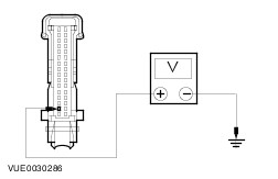
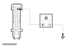
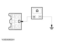
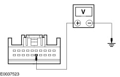
TEST the system for normal operation. | | PINPOINT TEST B : THE INSTRUMENT CLUSTER ILLUMINATION IS INOPERATIVE | | TEST CONDITIONS | DETAILS/RESULTS/ACTIONS | | B1: CHECK THE INSTRUMENT CLUSTER FOR POWER | | | 1 Disconnect Instrument Cluster C332. | | | 2 Turn the headlamp switch to the ON position. | | | 3 Measure the voltage between the instrument cluster C332 pin 15, circuit 29S-LK19 (OG/BU), harness side and ground. | | | Is the voltage greater than 10 volts? Yes No REPAIR circuit 29S-LK19 (OG/BU). TEST the system for normal operation. | | B2: CHECK THE INSTRUMENT CLUSTER FOR GROUND | | | 1 Measure the resistance between instrument the instrument cluster C332 pin 18, circuit 31-GG11 (BK), harness side and ground. | | | Is the resistance less than 5 ohms Yes INSTALL a new instrument cluster.
REFER to: Instrument Cluster - Vehicles Built Up To: 10/2005 (413-01 Instrument Cluster, Removal and Installation).
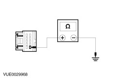
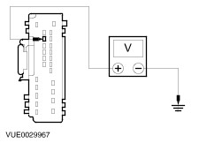
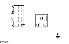
TEST the system for normal operation. No REPAIR circuit 31-GG11 (BK). TEST the system for normal operation. | | PINPOINT TEST C : THE CLIMATE CONTROL/INTEGRATED CONTROL PANEL ILLUMINATION IS INOPERATIVE - VEHICLES WITHOUT AIR CONDITIONING (A/C) | | TEST CONDITIONS | DETAILS/RESULTS/ACTIONS | | C1: CHECK THE CLIMATE CONTROL ASSEMBLY ILLUMINATION FOR POWER | | | 1 Disconnect Climate Control Assembly Illumination C620. | | | 2 Turn the headlamp switch to the ON position. | | | 3 Measure the voltage between the climate control assembly illumination C620 pin 1, circuit 29S-LH27 (OG/GN), harness side and ground. | | | Is the voltage greater than 10 volts? Yes No REPAIR circuit 29S-LH27 (OG/GN). TEST the system for normal operation. | | C2: CHECK THE CLIMATE CONTROL ASSEMBLY ILLUMINATION FOR GROUND | | | 1 Measure the resistance between climate control assembly illumination C620 pin 2, circuit 31-LH27 (BK), harness side and ground. | | | Is the resistance less than 5 ohms? Yes INSTALL a new climate control assembly.
REFER to: Climate Control Assembly - Vehicles Built From: 10/2005 (412-04 Control Components, Removal and Installation).
TEST the system for normal operation. No REPAIR circuit 31-LH27 (BK). TEST the system for normal operation. | | PINPOINT TEST D : THE CLIMATE CONTROL/INTEGRATED CONTROL PANEL ILLUMINATION IS INOPERATIVE - VEHICLES WITH A/C | | TEST CONDITIONS | DETAILS/RESULTS/ACTIONS | | D1: CHECK THE CLIMATE CONTROL ASSEMBLY ILLUMINATION FOR POWER | | | 1 Disconnect Climate Control Assembly C302. | | | 2 Turn the headlamp switch to the ON position. | | | 3 Measure the voltage between the climate control assembly C302 pin 8, circuit 29S-LH27 (OG/GN), harness side and ground. | | | Is the voltage greater than 10 volts? Yes No REPAIR circuit 29S-LH27 (OG/GN). TEST the system for normal operation. | | D2: CHECK THE CLIMATE CONTROL ASSEMBLY ILLUMINATION FOR GROUND | | | 1 Measure the resistance between climate control assembly C302 pin 10, circuit 31-LH27 (BK), harness side and ground. | | | Is the resistance less than 5 ohms? Yes INSTALL a new climate control assembly.
REFER to: Climate Control Assembly - Vehicles Built From: 10/2005 (412-04 Control Components, Removal and Installation).
TEST the system for normal operation. No REPAIR circuit 31-LH27 (BK). TEST the system for normal operation. | | PINPOINT TEST E : THE AUDIO UNIT ILLUMINATION IS INOPERATIVE | | TEST CONDITIONS | DETAILS/RESULTS/ACTIONS | | E1: CHECK THE AUDIO UNIT ILLUMINATION FOR POWER | | | 1 Disconnect Audio Unit C344. | | | 2 Turn the headlamp switch to the ON position. | | | 3 Measure the voltage between the audio unit C344 pin 3, circuit 29S-LK34 (OG/BK) or vehicles with cellular phone, circuit 29S-LK34 (VT/YE), harness side and ground. | | | Is the voltage greater than 10 volts? Yes No REPAIR circuit 29S-LK34 (OG/BK). TEST the system for normal operation. | | E2: CHECK THE AUDIO UNIT ILLUMINATION FOR GROUND | | | 1 Measure the resistance between the audio unit C344 pin 4, circuit 31-LK34 (BK), harness side and ground. | | | Is the resistance less than 5 ohms? Yes INSTALL a new audio unit.
REFER to: Audio Unit - Vehicles Built Up To: 10/2005 (415-01 Audio Unit, Removal and Installation).
TEST the system for normal operation. No REPAIR circuit 31-LK34 (BK). TEST the system for normal operation. | | PINPOINT TEST F : THE HAZARD LAMP SWITCH ILLUMINATION IS INOPERATIVE | | TEST CONDITIONS | DETAILS/RESULTS/ACTIONS | | F1: CHECK THE HAZARD LAMP SWITCH ILLUMINATION FOR POWER | | | 1 Disconnect Hazard Lamp Switch C321. | | | 2 Turn the headlamp switch to the ON position. | | | 3 Measure the voltage between the hazard lamp switch C321 pin 6, circuit 29S-LH54 (OG/GN), harness side and ground. | | | Is the voltage greater than 10 volts? Yes No REPAIR circuit 29S-LH54 (OG/GN). TEST the system for normal operation. | | F2: CHECK THE HAZARD LAMP SWITCH ILLUMINATION FOR GROUND | | | 1 Measure the resistance between the hazard lamp switch C321 pin 5, circuit 31-LG8 (BK), harness side and ground. | | | Is the resistance less than 5 ohms? Yes INSTALL a new hazard lamp switch. TEST the system for normal operation. No REPAIR circuit 31-LG8 (BK). TEST the system for normal operation. | | PINPOINT TEST G : THE MULTIFUNCTION SWITCH ASSEMBLY ILLUMINATION IS INOPERATIVE (AIR BAG DEACTIVATION WARNING, STABILITY ASSIST, FRONT WINDOW DEFROST OR REAR WINDOW DEFROST) | | TEST CONDITIONS | DETAILS/RESULTS/ACTIONS | | G1: CHECK THE MULTIFUNCTION SWITCH ASSEMBLY ILLUMINATION FOR POWER | | | 1 Disconnect Multifunction Switch Assembly C714. | | | 2 Turn the headlamp switch to the ON position. | | | 3 Measure the voltage between the multifunction switch assembly C714 pin 12, circuit 29S-DK1 (OG/YE), harness side and ground. | | | Is the voltage greater than 10 volts? Yes No REPAIR circuit 29S-DK1 (OG/YE). TEST the system for normal operation. | | G2: CHECK THE MULTIFUNCTION SWITCH ASSEMBLY ILLUMINATION FOR GROUND | | | 1 Measure the resistance between the multifunction switch assembly C714 pin 9, circuit 31-DK1 (BK), harness side and ground. | | | Is the resistance less than 5 ohms? Yes INSTALL a new multifunction switch assembly. TEST the system for normal operation. No REPAIR circuit 31-DK1 (BK). TEST the system for normal operation. | | PINPOINT TEST H : THE NAVIGATION SYSTEM DISPLAY MODULE ILLUMINATION IS INOPERATIVE | | TEST CONDITIONS | DETAILS/RESULTS/ACTIONS | | H1: CHECK THE NAVIGATION SYSTEM DISPLAY MODULE ILLUMINATION FOR POWER | | | 1 Disconnect Navigation System Display Module C717. | | | 2 Turn the headlamp switch to the ON position. | | | 3 Measure the voltage between the navigation system display module C717 pin 6, circuit 29S-LK34 (OG/BK), harness side and ground. | | | Is the voltage greater than 10 volts? Yes No REPAIR circuit 29S-LK34 (OG/BK). TEST the system for normal operation. | | H2: CHECK THE NAVIGATION SYSTEM DISPLAY MODULE ILLUMINATION FOR GROUND | | | 1 Measure the resistance between the navigation system display module C717 pin 8, circuit 91-MD15 (BK/GN), harness side and ground. | | | Is the resistance less than 5 ohms? Yes INSTALL a new navigation system display module. TEST the system for normal operation. No REPAIR circuit 91-MD15 (BK/GN). TEST the system for normal operation. | | PINPOINT TEST I : THE SELECTOR LEVER ILLUMINATION IS INOPERATIVE - VEHICLES WITH 4-SPEED AUTOMATIC TRANSAXLE (AW81-40LE) | | TEST CONDITIONS | DETAILS/RESULTS/ACTIONS | | I1: CHECK THE SELECTOR LEVER ILLUMINATION FOR POWER | | | 1 Disconnect Selector Lever C426. | | | 2 Turn the headlamp switch to the ON position. | | | 3 Measure the voltage between the selector lever C426 pin 4, circuit 29S-LK21 (OG/BK), harness side and ground. | | | Is the voltage greater than 10 volts? Yes No REPAIR circuit 29S-LK21 (OG/BK). TEST the system for normal operation. | | I2: CHECK THE SELECTOR LEVER ILLUMINATION FOR GROUND | | | 1 Measure the resistance between the selector lever C426 pin 1, circuit 31-TA35 (BK), harness side and ground. | | | Is the resistance less than 5 ohms? Yes INSTALL a new selector lever.
REFER to: Selector Lever Assembly (307-05 Automatic Transmission/Transaxle External Controls - Vehicles With: 4-Speed Automatic Transmission (AW81-40), Removal and Installation).
TEST the system for normal operation. No REPAIR circuit 31-TA35 (BK). TEST the system for normal operation. | | PINPOINT TEST J : THE GEARSHIFT LEVER ILLUMINATION IS INOPERATIVE - VEHICLES WITH AUTOMATED GEARSHIFT | | TEST CONDITIONS | DETAILS/RESULTS/ACTIONS | | J1: CHECK THE GEARSHIFT LEVER ILLUMINATION FOR POWER | | | 1 Disconnect Gearshift Lever C679. | | | 2 Turn the headlamp switch to the ON position. | | | 3 Measure the voltage between the gearshift lever C679 pin 11, circuit 29S-LK21 (OG/BK), harness side and ground. | | | Is the voltage greater than 10 volts? Yes No REPAIR circuit 29S-LK21 (OG/BK). TEST the system for normal operation. | | J2: CHECK THE GEARSHIFT LEVER ILLUMINATION FOR GROUND | | | 1 Measure the resistance between the gearshift lever C679 pin 12, circuit 91-TA35 (BK/GN), harness side and ground. | | | Is the resistance less than 5 ohms? Yes INSTALL a new gearshift lever.
REFER to: Gearshift Lever (308-06 Manual Transmission/Transaxle External Controls, Removal and Installation).
TEST the system for normal operation. No REPAIR circuit 91-TA35 (BK/GN). TEST the system for normal operation. | | PINPOINT TEST K : THE DVD PLAYER ILLUMINATION IS INOPERATIVE | | TEST CONDITIONS | DETAILS/RESULTS/ACTIONS | | K1: CHECK THE DVD PLAYER ILLUMINATION CIRCUIT FOR POWER | | | 1 Disconnect DVD Player C437. | | | 2 Turn the headlamp switch to the ON position. | | | 3 Measure the voltage between the DVD player C437 pin 15, circuit 29S-LK17 (OG/BK), harness side and ground. | | | Is the voltage greater than 10 volts? Yes No REPAIR circuit 29S-LK17 (OG-BK). Test the system for normal operation. | | K2: CHECK THE DVD PLAYER ILLUMINATION CIRCUIT FOR GROUND | | | 1 Measure the resistance between the DVD player C437 pin 16, 31-LK17 (BK), harness side and ground. | | | Is the resistance less than 1 ohm? Yes INSTALL a new DVD player. Test the system for normal operation. No Repair the circuit(s) 31-LK17 (BK). Test the system for normal operation. | |