| PINPOINT TEST A : REVERSING LAMPS INOPERATIVE |
| TEST CONDITIONS | DETAILS/RESULTS/ACTIONS |
| A1: NARROW DOWN THE FAULT CONDITION |
| | 1 Ignition switch in position II. |
| | 2 Engage reverse gear. |
| | 3 CHECK the reversing lamps. |
| | Is the left-hand reversing lamp inoperative? Yes The left-hand reversing lamp is inoperative: GO to A12. No - The right-hand reversing lamp is inoperative: GO to A14. - Both reversing lamps are inoperative: GO to A2. |
| A2: CHECK FUSE F48 (7.5 A) (CJB). |
| | 1 Ignition switch in position 0. |
| | 2 Disconnect fuse F48 (7.5 A) (CJB). |
| | 3 CHECK fuse F48 (7.5 A) (CJB). |
| | Is the fuse OK.? Yes No RENEW fuse F48 (7.5 A) (CJB) and check the operation of the system. If the fuse blows again, LOCATE and RECTIFY the short to ground using the Wiring Diagrams. CHECK the operation of the system. |
| A3: CHECK THE VOLTAGE SUPPLY TO FUSE F48 (7.5 A) (CJB) FOR OPEN CIRCUIT |
| | 1 Connect fuse F48 (7.5 A) (CJB). |
| | 2 Ignition switch in position II. |
| | 3 Measure the voltage between fuse F48 (7.5 A) (CJB) and ground. |
| | Does the meter display battery voltage? Yes - Vehicles with manual transmission and with Durashift EST: GO to A4. - Vehicles with 4-speed automatic transmission (AW81-40): GO to A6. No LOCATE AND RECTIFY the break in the voltage supply to fuse F48 (7.5 A) (CJB) using the Wiring Diagrams. If necessary RENEW the CJB. CHECK the operation of the system. |
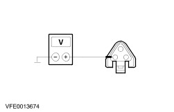
| A4: CHECK VOLTAGE SUPPLY TO THE REVERSING LAMP SWITCH FOR OPEN CIRCUIT |
| | 1 Ignition switch in position 0. |
| | 2 Disconnect reversing lamp switch from connector C425. |
| | 3 Ignition switch in position II. |
| | 4 Measure the voltage between the reversing lamp switch, connector C425, pin 1, circuit 15-LG28 (GN/WH), wiring harness side and ground. |
| | Does the meter display battery voltage? Yes No LOCATE and RECTIFY the break in the circuit between fuse F48 (7.5 A) (CJB) and the reversing lamp switch using the Wiring Diagrams. CHECK the operation of the system. |
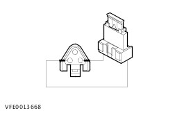
| A5: CHECK REVERSING LAMP SWITCH |
| | 1 Ignition switch in position 0. |
| | 2 Connect a fused jumper wire (7.5 A) to the reversing lamp switch, connector C425, between pin 1, circuit 15-LG28 (GN/WH) and - On petrol engines: pin 2, circuit 15S-LG1 (GN/YE), wiring harness side.
- On diesel engines: pin 2, circuit 15S-LG5 (GN/RD), wiring harness side.
|
| | 3 Ignition switch in position II. |
| | 4 CHECK the operation of the reversing lamps. |
| | Do the reversing lamps illuminate? Yes INSTALL A NEW reversing lamp switch. CHECK the operation of the system. No LOCATE and RECTIFY the break in the circuits between the reversing lamp switch and soldered connection S32 using the Wiring Diagrams. CHECK the operation of the system. |
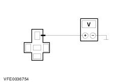
| A6: CHECK VOLTAGE SUPPLY TO THE REVERSING LAMP RELAY FOR OPEN CIRCUIT |
| | 1 Ignition switch in position 0. |
| | 2 Disconnect reversing lamp relay from socket C434. |
| | 3 Ignition switch in position II. |
| | 4 Measure the voltage between the reversing lamp relay, socket C434, pin 3, circuit 15-LG28 (GN/WH)/15-TC6 (GN/YE), socket side and ground. |
| | Does the meter display battery voltage? Yes No LOCATE and RECTIFY the break in the circuit between fuse F48 (7.5 A) (CJB) and the reversing lamp relay using the Wiring Diagrams. CHECK the operation of the system. |
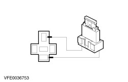
| A7: NARROW DOWN THE CAUSE OF THE FAULT |
| | 1 Ignition switch in position 0. |
| | 2 Connect a fused jumper wire (7.5 A) at reversing lamp relay, socket C434, between pin 3, circuit 15-LG28 (GN/WH)/15-TC6 (GN/YE), socket side and pin 5, circuit 15S-LG1 (GN/YE), socket side. |
| | 3 Ignition switch in position II. |
| | 4 CHECK the reversing lamps. |
| | Do the reversing lamps illuminate? Yes No LOCATE and RECTIFY the break in the circuits between the reversing lamp relay and soldered connection S32 using the Wiring Diagrams. CHECK the operation of the system. |
| A8: CHECK CIRCUIT 15S-TC6 (GN/YE) FOR OPEN CIRCUIT |
| | 1 Measure the voltage between the reversing lamp relay, socket C434, pin 1, circuit 15-TC6 (GN/YE), socket side and ground. |
| | Does the meter display battery voltage? Yes No LOCATE and RECTIFY the break in the circuit at the reversing lamp relay, socket C434, between pin 1 and pin 3 using the Wiring Diagrams. If necessary RENEW the engine compartment relay box. CHECK the operation of the system. |
| A9: CHECK THE REVERSING LAMP RELAY |
| | 1 ENGAGE reverse gear |
| | 2 Measure the voltage between the reversing lamp relay, socket C434, pin 1, circuit 15-TC6 (GN/YE), socket side and pin 2, circuit 91S-TC6 (BK/YE), socket side. |
| | Does the meter display battery voltage? Yes RENEW the reversing lamp relay. CHECK the operation of the system. No |
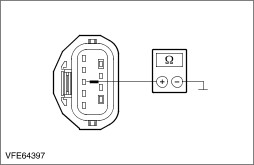
| A10: CHECK THE CONTROL CIRCUIT BETWEEN THE SHIFT LEVER POSITION SENSOR AND THE REVERSING LAMP RELAY FOR OPEN CIRCUIT |
| | 1 Ignition switch in position 0. |
| | 2 Disconnect Shift lever position sensor from connector C431. |
| | 3 Measure the resistance between the reversing lamp relay, socket C434, pin 2, circuit 91S-TC6 (BK/YE), socket side and the shift lever position sensor, connector C431, pin 2, circuit 91S-TA1 (BK/BU), wiring harness side. |
| | Is a resistance of less than 2 ohms registered? Yes No LOCATE and RECTIFY the break in the circuit between the reversing lamp relay and the shift lever position sensor using the Wiring Diagrams. CHECK the operation of the system. |
| A11: RULE OUT THE SHIFT LEVER POSITION SENSOR AS THE CAUSE OF THE FAULT |
| | 1 Measure the resistance between the shift lever position, connector C431, pin 3, circuit 91-TA18 (BK/RD), wiring harness side and ground. |
| | Is a resistance of less than 2 ohms registered? Yes RENEW the shift lever position sensor. CHECK the operation of the system. No LOCATE and RECTIFY the break in the circuit between the shift lever position sensor and soldered connection S132 using the Wiring Diagrams. CHECK the operation of the system. |
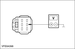
| A12: CHECK THE VOLTAGE SUPPLY TO THE LEFT-HAND REAR LAMP ASSEMBLY FOR OPEN CIRCUIT |
| | 1 Ignition switch in position 0. |
| | 2 Disconnect Left-hand rear lamp assembly. - Vehicles without trailer socket: from connector C333
- Vehicles with trailer socket: from connector C333a
|
| | 3 Ignition switch in position II. |
| | 4 Engage reverse gear. |
| | 5 Measure the voltage between the left-hand rear lamp assembly - Vehicles without trailer socket: connector C333, pin 5, circuit 15S-LG39B (GN/OG), wiring harness side and ground.
- Vehicles with trailer socket: Connector C333a, pin 5, circuit (VT/YE), wiring harness side and ground.
|
| | Does the meter display battery voltage? Yes No LOCATE and RECTIFY the break in the circuits between soldered connection S32 and the rear lamp assembly using the Wiring Diagrams. CHECK the operation of the system. |
| A13: CHECK THE GROUND CONNECTION TO THE LEFT-HAND REAR LAMP ASSEMBLY FOR OPEN CIRCUIT |
| | 1 Ignition switch in position 0. |
| | 2 Measure the resistance between left-hand rear lamp assembly - Vehicles without trailer socket: connector C333, pin 4, circuit 31-LF23 (BK), wiring harness side and ground.
- Vehicles with trailer socket: connector C333a, pin 4, circuit (BN), wiring harness side and ground.
|
| | Is a resistance of less than 2 ohms registered? Yes CHECK and if necessary RENEW the rear lamp assembly. CHECK the operation of the system. No LOCATE and RECTIFY the break in the circuits between the rear lamp assembly and soldered connection S24 using the Wiring Diagrams. CHECK the operation of the system. |
| A14: CHECK VOLTAGE SUPPLY TO THE RIGHT-HAND REAR LAMP ASSEMBLY FOR OPEN CIRCUIT |
| | 1 Ignition switch in position 0. |
| | 2 Disconnect Right-hand rear lamp assembly. - Vehicles without trailer socket: from connector C348
- Vehicles with trailer socket: from connector C348a
|
| | 3 Ignition switch in position II. |
| | 4 Engage reverse gear. |
| | 5 Measure the voltage between the right-hand rear lamp assembly - Vehicles without trailer socket: connector C348, pin 5, circuit 15S-LG39A (GN/OG), wiring harness side and ground.
- Vehicles with trailer socket: connector C348a, pin 5, circuit (WH/BK), wiring harness side and ground.
|
| | Does the meter display battery voltage? Yes No LOCATE and RECTIFY the break in the circuits between soldered connection S32 and the rear lamp assembly using the Wiring Diagrams. CHECK the operation of the system. |
| A15: CHECK THE GROUND CONNECTION TO THE RIGHT-HAND REAR LAMP ASSEMBLY FOR OPEN CIRCUIT |
| | 1 Ignition switch in position 0. |
| | 2 Measure the resistance between the right-hand rear lamp assembly - Vehicles without trailer socket: connector C348, pin 4, circuit 31-LF24 (BK), wiring harness side and ground.
- Vehicles with trailer socket: connector C348a, pin 4, circuit (WH/BK), wiring harness side and ground.
|
| | Is a resistance of less than 2 ohms registered? Yes CHECK and if necessary RENEW the rear lamp assembly. CHECK the operation of the system. No LOCATE and RECTIFY the break in the circuits between the rear lamp assembly and ground connection G18 using the Wiring Diagrams. CHECK the operation of the system. |