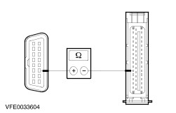
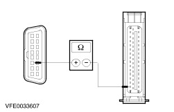
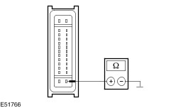
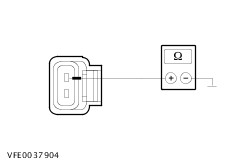
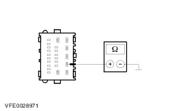
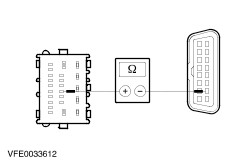
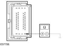
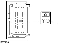
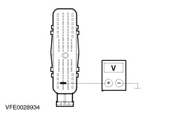
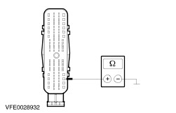
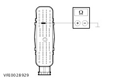
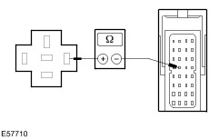
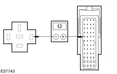
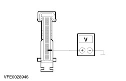
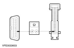
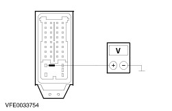
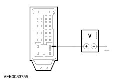
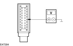
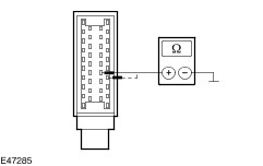
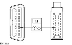
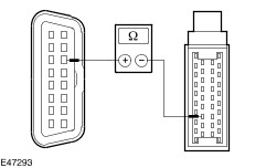
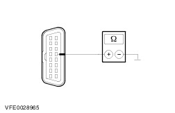
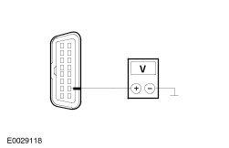
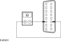
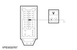
| Diagnosis and Testing Special Tool(s) | | Terminal Probe Kit 29-011A | General Equipment Digital Multimeter Worldwide Diagnostic System (WDS) Inspection and Checking - Visually CHECK for any obvious mechanical or electrical damage.
Visual Inspection | Electrical | - Fuse(s).
- Wiring harness.
- Plugs.
| - RECTIFY any obvious causes for a concern found during the visual inspection before performing any further tests. CHECK the operation of the system.
- If the concern persists after the visual inspection, PERFORM a fault diagnosis with WDS and RECTIFY any displayed faults in accordance with the displayed fault description. CHECK the operation of the system.
- For vehicles with no stored fault(s), PROCEED in accordance with the symptom chart according to the fault symptom.
- Following checking or elimination of the fault and after completion of operations, the fault memories of all vehicle modules must be READ OUT and any stored faults must be DELETED. READ OUT all fault memories again following a road test.
Symptom Chart Symptom Chart | Symptom | Possible Sources | Action | | Safety restraint control module (RCM) not communicating with the diagnostic unit | * Fuse(s). * Circuit(s). * Restraints control module (RCM). | * | | ABS module or ESP module not communicating with the diagnostic unit | * Fuse(s). * Circuit(s). * ABS module or ESP module. | * | | Generic electronic module (GEM) not communicating with the diagnostic tester | * Fuse(s). * Circuit(s). * Generic electronic module (GEM). | * | | Powertrain control module (PCM) not communicating with the diagnostic tester | * Fuse(s). * Circuit(s). * PCM. | * | | Power steering pump module not communicating with the diagnostic tester | * Fuse(s). * Circuit(s). * Power steering pump module. | * | | Instrument cluster not communicating with the diagnostic unit | * Fuse(s). * Circuit(s). * Instrument cluster. | * | | Transmission control module (TCM) not communicating with the diagnostic tester | * Fuse(s). * Circuit(s). * TCM. | * - Vehicles with automatic clutch and gearshift actuation: GO to Pinpoint Test G. * - Vehicles with automatic transmission: GO to Pinpoint Test H. | | Faulty communication between the modules (ISO 9141 bus) | * Circuit(s). * Generic electronic module (GEM). * Restraints control module (RCM). * ABS module or ESP module. | * | | Faulty communication between the modules (CAN bus) | * Circuit(s). * Instrument cluster. * ABS module or ESP module. * Transmission control module (TCM) - vehicles with automatic clutch and gearshift actuation. * Transmission selector unit - vehicles with automatic clutch and gearshift actuation. * Transmission control unit (TCM) - vehicles with automatic transmission * Power steering pump module. * Powertrain control module (PCM). | * | System Checks | PINPOINT TEST A : SAFETY RESTRAINT CONTROL MODULE (RCM) NOT COMMUNICATING WITH THE DIAGNOSTIC UNIT | WARNING:The backup power supply must be depleted to prevent the risk of accidental airbag deployment. After disconnecting the battery, wait at least 1 minute before starting work on the safety restraint system. Failure to observe this instruction can lead to injury. | WARNING:Do not program any keycodes while working on the safety restraint system in order to prevent the risk of accidental deployment of safety restraint system components. Failure to observe this instruction can lead to injury. | WARNING:Only test the connectors of airbags or other safety restraint systems using the correct test probe adapter. Failure to observe this instruction can lead to injury. | | TEST CONDITIONS | DETAILS/RESULTS/ACTIONS | | A1: DETERMINE THE CONDITIONS UNDER WHICH THE FAULT OCCURS | | | 1 Ignition switch in position 0. | | | 2 Connect the diagnostic tool. | | | 3 Select the generic electronic module (GEM) with the diagnostic tester. | | | Is it possible to establish communication with the GEM? Yes No | | A2: CHECK FUSE F39 | | | 1 Ignition switch in position 0. | | | 2 CHECK fuse F39 (CJB). | | | Is the fuse OK? Yes No INSTALL A NEW fuse F39 (7.5 A). CHECK the operation of the system. If the fuse blows again, LOCATE and REPAIR the short using the Wiring Diagrams. | | A3: CHECK THE VOLTAGE AT FUSE F39 | | | 1 Connect fuse F39 (CJB). | | | 2 Ignition switch in position II. | | | 3 Measure the voltage between fuse F39 (7.5 A) and ground. | | | Does the meter display battery voltage? Yes No REPAIR the voltage supply to fuse F39 using the Wiring Diagrams. CHECK the operation of the system. | | A4: CHECK THE VOLTAGE AT THE SAFETY RESTRAINT CONTROL MODULE (RCM) | | | 1 Ignition switch in position 0. | | | 2 Disconnect the ground cable from the battery. | | | 3 Disconnect connector C500 from safety restraint control module (RCM). | | | 4 Connect the ground cable to the battery. | | | 5 Ignition switch in position II. | | | 6 Measure the voltage between the safety restraint control module (RCM), connector C500, pin 1, circuit 15-JA10 (GN/OG), wiring harness side and ground. | | | Does the meter display battery voltage? Yes No LOCATE and REPAIR the break in circuit 15-JA10 (GN/OG) between the safety restraint control module (RCM) and fuse F39 using the Wiring Diagrams. CHECK the operation of the system. | | A5: CHECK THE GROUND CONNECTION OF THE SAFETY RESTRAINT CONTROL MODULE (RCM) | | | 1 Ignition switch in position 0. | | | 2 Measure the resistance between the safety restraint control module (RCM), connector C500, pin 20, circuit 91-JA10 (BK/RD), wiring harness side and ground. | | | Is a resistance of less than 2 Ohm registered? Yes - All, except vehicles built for Japan: GO to A7. No LOCATE and REPAIR the break in circuit 91-JA10 (BK/RD) between the safety restraint control module (RCM) and ground connection G21 using the Wiring Diagrams. CHECK the operation of the system. | | A6: CHECK THE GROUND CONNECTION OF THE SAFETY RESTRAINT CONTROL MODULE (RCM) | | | 1 Measure the resistance between the safety restraint control module (RCM), connector C500, pin 21, circuit 91-JA47A (BK/OG), wiring harness side and ground. | | | Is a resistance of less than 2 Ohm registered? Yes No LOCATE and REPAIR the break in the circuit between the safety restraint control module (RCM) and ground connection G21 using the Wiring Diagrams. CHECK the operation of the system. | | A7: CHECK FOR OPEN CIRCUIT BETWEEN THE SAFETY RESTRAINT CONTROL MODULE (RCM) AND THE DATA LINK CONNECTOR (DLC) | | | 1 Measure the resistance between the safety restraint control module (RCM), connector C500, pin 17, circuit 4-EE7 (GY/RD), wiring harness side and the DLC, C308, pin 7, circuit 4-EE10 (GY/BK), wiring harness side. | | | Is a resistance of less than 2 Ohm registered? Yes CHECK and if necessary RENEW the safety restraint control module (RCM). CHECK the operation of the system. No LOCATE and REPAIR the break in circuit 4-EE7 (GY/RD) between the safety restraint control module (RCM) and soldered connection S270 using the Wiring Diagrams. CHECK the operation of the system. | | PINPOINT TEST B : ABS MODULE OR ESP MODULE NOT COMMUNICATING WITH THE DIAGNOSTIC UNIT | | TEST CONDITIONS | DETAILS/RESULTS/ACTIONS | | B1: DETERMINE THE CONDITIONS UNDER WHICH THE FAULT OCCURS | | | 1 Ignition switch in position 0. | | | 2 Connect the diagnostic tool. | | | 3 Select the generic electronic module (GEM) with the diagnostic tester. | | | Is it possible to establish communication with the GEM? Yes No | | B2: CHECK FUSE F5 | | | 1 Ignition switch in position 0. | | | 2 CHECK fuse F5 (CJB). | | | Is the fuse OK? Yes No INSTALL A NEW fuse F5 (20 A). CHECK the operation of the system. If the fuse blows again, LOCATE and REPAIR the short using the Wiring Diagrams. | | B3: CHECK THE VOLTAGE AT FUSE F5 | | | 1 Connect fuse F5 (CJB). | | | 2 Measure the voltage between fuse F5 (20 A) and ground. | | | Does the meter display battery voltage? Yes No | | B4: CHECK FUSE FH | | | 1 Ignition switch in position 0. | | | 2 CHECK fuse FH (BJB). | | | Is the fuse OK? Yes No RENEW fuse FH (60 A). CHECK the operation of the system. If the fuse blows again, LOCATE and REPAIR the short using the Wiring Diagrams. | | B5: CHECK THE VOLTAGE AT FUSE FH | | | 1 Connect fuse FH (BJB). | | | 2 Measure the voltage between fuse FH (60 A) and ground. | | | Does the meter display battery voltage? Yes No REPAIR the voltage supply to fuse FH using the Wiring Diagrams. CHECK the operation of the system. | | B6: CHECK FOR OPEN CIRCUIT BETWEEN FUSE FH AND FUSE F5 | | | 1 Disconnect connector C1001 from BJB. | | | 2 Measure resistance between BJB, connector C1001, circuit 30S-DB5 (RD), wiring harness side and fuse F5 (CJB), wiring harness side. | | | Is a resistance of less than 2 Ohm registered? Yes CHECK the BJB and INSTALL a new one as necessary. CHECK the operation of the system. No LOCATE and REPAIR the break in circuit 30-DB8 (RD) between fuse FH and fuse F5 using the Wiring Diagrams. CHECK the operation of the system. | | B7: CHECK FUSE F37 | | | 1 CHECK fuse F37 (CJB). | | | Is the fuse OK? Yes No INSTALL A NEW fuse F37 (3 A). CHECK the operation of the system. If the fuse blows again, LOCATE and REPAIR the short using the Wiring Diagrams. | | B8: CHECK THE VOLTAGE AT FUSE F37 | | | 1 Connect fuse F37 (CJB). | | | 2 Ignition switch in position II. | | | 3 Measure the voltage between fuse F37 (3 A) and ground. | | | Does the meter display battery voltage? Yes - Vehicles with ABS built up to 03/2004 or with electronic stability program (ESP) GO to B15. - Vehicles with ABS built from 04/2004 onwards GO to B20. No | | B9: CHECK THE VOLTAGE AT THE IGNITION RELAY | | | 1 Ignition switch in position 0. | | | 2 Disconnect ignition relay from socket C328. | | | 3 Measure the voltage between the ignition relay, socket C328, pin 3, circuit 30-BB8 (RD), wiring harness side and ground. | | | Does the meter display battery voltage? Yes No | | B10: CHECK FUSE FF | | | 1 Ignition switch in position 0. | | | 2 CHECK fuse FF (BJB). | | | Is the fuse OK? Yes No RENEW fuse FF (60 A). CHECK the operation of the system. If the fuse blows again, LOCATE and REPAIR the short using the Wiring Diagrams. | | B11: CHECK THE VOLTAGE AT FUSE FF | | | 1 Connect fuse FF (BJB). | | | 2 Measure the voltage between fuse FF (60 A) and ground. | | | Does the meter display battery voltage? Yes LOCATE and REPAIR the break in circuit 30-BB8 (RD) between the ignition relay and fuse FF using the Wiring Diagrams. CHECK the operation of the system. No REPAIR the voltage supply to fuse FF using the Wiring Diagrams. CHECK the operation of the system. | | B12: CHECK THE VOLTAGE AT THE IGNITION RELAY | | | 1 Ignition switch in position II. | | | 2 Measure the voltage between the ignition relay, socket C328, pin 1, circuit 15-BB7 (GN/BU), wiring harness side and ground. | | | Does the meter display battery voltage? Yes No LOCATE and RECTIFY the break in the circuit between the ignition relay and the ignition switch using the Wiring Diagrams. CHECK the operation of the system. | | B13: CHECK GROUND CONNECTION AT IGNITION RELAY | | | 1 Measure the resistance between the ignition relay, socket C328, pin 2, circuit 91S-RH9 (BK/BU), wiring harness side and ground. | | | Is a resistance of less than 2 Ohm registered? Yes No LOCATE and RECTIFY the break in the circuit between the ignition relay and soldered connection S109 using the Wiring Diagrams. CHECK the operation of the system. | | B14: CHECK CIRCUIT BETWEEN THE IGNITION RELAY AND FUSE F37 FOR OPEN CIRCUIT | | | 1 Measure the resistance between the ignition relay, socket C328, pin 5, circuit 15-DB2 (GN/BU), wiring harness side and fuse F37 (CJB). | | | Is a resistance of less than 2 Ohm registered? Yes CHECK and if necessary RENEW the ignition relay. CHECK the operation of the system. No LOCATE and REPAIR the open circuit between the ignition relay and fuse F37 using the Wiring Diagrams. CHECK the operation of the system. | | B15: CHECK THE VOLTAGE AT THE ABS MODULE OR ESP MODULE | | | 1 Ignition switch in position 0. | | | 2 Disconnect Connector C303 from ABS module or ESP module. | | | 3 Measure the voltage between the ABS module or ESP module, connector C303, pin 32, circuit 29-CF6 (OG/YE), wiring harness side and ground. | | | Does the meter display battery voltage? Yes No LOCATE and REPAIR break in circuit 29-CF6 (OG/YE) between the ABS module or ESP module and fuse F5 using the Wiring Diagrams. CHECK the operation of the system. | | B16: CHECK THE VOLTAGE AT THE ABS MODULE OR ESP MODULE | | | 1 Ignition switch in position II. | | | 2 Measure the voltage between the ABS module or ESP module, connector C303, pin 4, circuit 15-CF6 (GN/YE), wiring harness side and ground. | | | Does the meter display battery voltage? Yes No LOCATE and REPAIR break in circuit 15-CF6 (GN/YE) between the ABS module or ESP module and fuse F37 using the Wiring Diagrams. CHECK the operation of the system. | | B17: CHECK THE GROUND CONNECTION OF THE ABS MODULE OR ESP MODULE | | | 1 Ignition switch in position 0. | | | 2 Measure the resistance between the ABS module or ESP module, connector C303, pin 16, circuit 31-CF6 (BK), wiring harness side and ground. | | | Is a resistance of less than 2 Ohm registered? Yes No LOCATE and REPAIR the break in the circuit between the ABS module or ESP module and ground connection G23 using the Wiring Diagrams. CHECK the operation of the system. | | B18: CHECK FOR OPEN CIRCUIT BETWEEN THE ABS MODULE OR ESP MODULE AND THE DLC | | | 1 Measure the resistance between the DLC, connector C308, pin 6, circuit 4-EC1 (GY/RD), wiring harness side and the ABS module or ESP module, connector C303, pin 11, circuit 4-EC9 (GY), wiring harness side. | | | 2 Measure the resistance between the DLC, connector C308, pin 14, circuit 5-EC1 (BU/RD), wiring harness side and the ABS module or ESP module, connector C303, pin 15, circuit 5-EC9 (BU), wiring harness side. | | | Is a resistance of less than 2 Ohms measured in both cases? Yes No LOCATE and REPAIR the break in the relevant circuit between the ABS module or ESP module and DLC using the Wiring Diagrams. CHECK the operation of the system. | | B19: CHECK FOR OPEN CIRCUIT BETWEEN THE ABS MODULE OR ESP MODULE AND THE DATA LINK CONNECTOR (DLC) | | | 1 Measure the resistance between the ABS module or ESP module, connector C303, pin 2, circuit 4-EE6 (GY), wiring harness side and DLC, C308, pin 7, circuit 4-EE10 (GY/BK), wiring harness side. | | | Is a resistance of less than 2 Ohm registered? Yes CHECK and if necessary RENEW the ABS module or ESP module. CHECK the operation of the system. No LOCATE and REPAIR the break in the circuit between the ABS module or ESP module and soldered connection S270 using the Wiring Diagrams. CHECK the operation of the system. | | B20: CHECK THE VOLTAGE AT THE ABS MODULE | | | 1 Ignition switch in position 0. | | | 2 Disconnect connector C304 from ABS module. | | | 3 Measure the voltage between the ABS module, connector C304, pin 1, circuit 29-CF6 (OG/YE), wiring harness side and ground. | | | Does the meter display battery voltage? Yes No LOCATE and REPAIR the break in circuit 29-CF6 (OG/YE) between the ABS module and fuse F5 using the Wiring Diagrams. CHECK the operation of the system. | | B21: CHECK THE VOLTAGE AT THE ABS MODULE | | | 1 Ignition switch in position II. | | | 2 Measure the voltage between the ABS module, connector C304, pin 20, circuit 15-CF6 (GN/YE), wiring harness side and ground. | | | Does the meter display battery voltage? Yes No LOCATE and REPAIR the break in circuit 15-CF6 (GN/YE) between the ABS module and fuse F37 using the Wiring Diagrams. CHECK the operation of the system. | | B22: CHECK THE GROUND CONNECTION OF THE ABS MODULE | | | 1 Ignition switch in position 0. | | | 2 Measure the resistance between the ABS module, connector C304, pin 26, circuit 31-CF6 (BK), wiring harness side and ground. | | | Is a resistance of less than 2 Ohm registered? Yes No LOCATE and REPAIR the break in the circuit between the ABS module and ground connection G23 using the wiring diagrams. CHECK the operation of the system. | | B23: CHECK FOR OPEN CIRCUIT BETWEEN THE ABS MODULE AND THE DLC | | | 1 Measure the resistance between the DLC, connector C308, pin 6, circuit 4-EC1 (GY/RD), wiring harness side and the ABS module, connector C304, pin 23, circuit 4-EC9 (GY), wiring harness side. | | | 2 Measure the resistance between the DLC, connector C308, pin 14, circuit 5-EC1 (BU/RD), wiring harness side and the ABS module, connector C304, pin 21, circuit 5-EC9 (BU), wiring harness side. | | | Is a resistance of less than 2 Ohms measured in both cases? Yes No LOCATE and REPAIR the break in the corresponding circuit between the ABS module and the DLC using the Wiring Diagrams. CHECK the operation of the system. | | B24: CHECK THE CIRCUIT BETWEEN THE ABS MODULE AND THE DATA LINK CONNECTOR (DLC) FOR OPEN CIRCUIT | | | 1 Measure the resistance between the ABS module, connector C304, pin 18, circuit 4-EE6 (GY), wiring harness side and DLC, connector C308, pin 7, circuit 4-EE10 (GY/BK), wiring harness side. | | | Is a resistance of less than 2 Ohm registered? Yes CHECK the ABS module and if necessary INSTALL a new one. CHECK the operation of the system. No LOCATE and REPAIR the break in the circuit between the ABS module and soldered connection S270 using the wiring diagrams. CHECK the operation of the system. | | PINPOINT TEST C : POWER STEERING PUMP MODULE NOT COMMUNICATING WITH THE DIAGNOSTIC TESTER | | TEST CONDITIONS | DETAILS/RESULTS/ACTIONS | | C1: DETERMINE THE CONDITIONS UNDER WHICH THE FAULT OCCURS | | | 1 Ignition switch in position 0. | | | 2 Connect the diagnostic tool. | | | 3 Select the generic electronic module (GEM) with the diagnostic tester. | | | Is it possible to establish communication with the GEM? Yes No | | C2: TEST FUSE FA | | | 1 Ignition switch in position 0. | | | 2 CHECK Fuse FA (BJB). | | | Is the fuse OK? Yes No RENEW fuse FA (80 A). CHECK the operation of the system. If the fuse blows again, LOCATE and REPAIR the short using the Wiring Diagrams. | | C3: TEST VOLTAGE AT FUSE FA | | | 1 Connect Fuse FA (BJB). | | | 2 Measure the voltage between fuse FA (80A) and ground. | | | Is battery voltage measured? Yes No REPAIR the voltage supply to fuse FA with the aid of the Wiring Diagrams. CHECK the operation of the system. | | C4: CHECK THE VOLTAGE AT THE POWER STEERING PUMP MODULE | | | 1 Disconnect Connector C280 from the power steering pump module. | | | 2 Measure the voltage between the power steering pump module, connector C280, pin 1, circuit 30-CE7 (RD), wiring harness side and ground. | | | Is battery voltage measured? Yes No LOCATE and REPAIR the break in circuit 30-CE7 (RD), between the power steering pump module and fuse FA using the Wiring Diagrams. CHECK the operation of the system. | | C5: CHECK THE VOLTAGE AT THE POWER STEERING PUMP MODULE | | | 1 Disconnect Connector C281 from the power steering pump module. | | | 2 Ignition switch in position II. | | | 3 Measure the voltage between the power steering pump module, connector C281, pin 1, circuit 15-CE7 (GN/BU), wiring harness side and ground. | | | Is battery voltage measured? Yes No LOCATE and REPAIR the break in circuit 15-CE7 (GN/BU), between the power steering pump module and soldered connection S138 using the Wiring Diagrams. CHECK the operation of the system. | | C6: CHECK THE GROUND CONNECTION OF THE POWER STEERING PUMP MODULE | | | 1 Ignition switch in position 0. | | | 2 Measure the resistance between the power steering pump module, connector C280, pin 2, circuit 31-CE7 (BK), wiring harness side and ground. | | | Is a resistance of less than 2 Ohms registered? Yes No LOCATE and REPAIR the break in circuit 31-CE7 (BK), between the power steering pump module and ground connection G32 using the Wiring Diagrams. CHECK the operation of the system. | | C7: CHECK FOR OPEN CIRCUIT BETWEEN THE POWER STEERING PUMP MODULE AND THE DATA LINK CONNECTOR (DLC) | | | 1 Measure the resistance between the power steering pump module, connector C281, pin 3, circuit 4-EC8B (GY/VT), wiring harness side and the DLC, connector C308, pin 6, circuit 4-EC1 (GY/RD), wiring harness side. | | | Is a resistance of less than 2 Ohms registered? Yes No LOCATE and REPAIR the break in circuit 4-EC8B (GY/VT) between the power steering pump module and soldered connection S130 using the Wiring Diagrams. CHECK the operation of the system. | | C8: CHECK FOR OPEN CIRCUIT BETWEEN THE POWER STEERING PUMP MODULE AND THE DATA LINK CONNECTOR (DLC) | | | 1 Measure the resistance between the power steering pump module, connector C281, pin 2, circuit 5-EC8B (BU/WH), wiring harness side and the DLC, connector C308, pin 14, circuit 5-EC1 (BU/RD), wiring harness side. | | | Is a resistance of less than 2 Ohms registered? Yes CHECK and if necessary RENEW the power steering pump module. CHECK the operation of the system. No LOCATE and REPAIR the break in circuit 5-EC8B (BU/WH) between the power steering pump module and soldered connection S131 using the Wiring Diagrams. CHECK the operation of the system. | | PINPOINT TEST D : GENERIC ELECTRONIC MODULE (GEM) NOT COMMUNICATING WITH THE DIAGNOSTIC TESTER | | TEST CONDITIONS | DETAILS/RESULTS/ACTIONS | | D1: DETERMINE THE FAULT CONDITION | | | 1 Ignition switch in position 0. | | | 2 Connect the diagnostic tool. | | | 3 Select the safety restraint control module (RCM) with the diagnostic tester. | | | Is it possible to establish communication with the safety restraint control module (RCM)? Yes No | | D2: CHECK FUSE F38 | | | 1 Ignition switch in position 0. | | | 2 CHECK fuse F38 (CJB). | | | Is the fuse OK? Yes No INSTALL A NEW fuse F38 (7.5 A). CHECK the operation of the system. If the fuse blows again, LOCATE and REPAIR the short using the Wiring Diagrams. | | D3: CHECK THE VOLTAGE AT FUSE F38 | | | 1 Connect fuse F38 (CJB). | | | 2 Ignition switch in position II. | | | 3 Measure the voltage between fuse F38 (7.5 A) and ground. | | | Does the meter display battery voltage? Yes No REPAIR the voltage supply to fuse F38 using the Wiring Diagrams. CHECK the operation of the system. | | D4: CHECK THE VOLTAGE AT THE GEM | | | 1 Ignition switch in position 0. | | | 2 Disconnect connector C319 (white) from GEM. | | | 3 Ignition switch in position II. | | | 4 Measure the voltage between the GEM, connector C319 (white), pin 10, circuit 15-DK20 (GN/OG), wiring harness side and ground. | | | Does the meter display battery voltage? Yes No LOCATE and REPAIR the break in circuit 15-DK20 (GN/OG) between the GEM and soldered connection S3 using the Wiring Diagrams. CHECK the operation of the system. | | D5: TEST THE GEM GROUND CONNECTION | | | 1 Ignition switch in position 0. | | | 2 Disconnect connector C316 (black) from GEM. | | | 3 Measure the resistance between the GEM, connector C316 (black), pin 2, circuit 31-DK20 (BK), wiring harness side and ground. | | | Is a resistance of less than 2 Ohm registered? Yes No LOCATE and REPAIR the break in circuit 31-DK20 (BK) between the GEM and soldered connection S15 using the Wiring Diagrams. CHECK the operation of the system. | | D6: TEST THE GEM GROUND CONNECTION | | | 1 Disconnect connector C320 (brown) from GEM. | | | 2 Measure the resistance between the GEM, connector C320 (brown), pin 2, circuit 91-DK20 (BK/RD), wiring harness side and ground. | | | Is a resistance of less than 2 Ohm registered? Yes No LOCATE and RECTIFY the break in circuit 91-DK20 (BK/RD) between the GEM and ground connection G14 using the Wiring Diagrams. CHECK the operation of the system. | | D7: CHECK FOR OPEN CIRCUIT BETWEEN THE GEM AND THE DLC. | | | 1 Measure the resistance between GEM, connector C320 (brown), pin 10, circuit 4-EE11 (GY/WH), wiring harness side and DLC, C308, pin 7, circuit 4-EE10 (GY/BK), wiring harness side. | | | Is a resistance of less than 2 Ohm registered? Yes TEST the GEM and RENEW as necessary. CHECK the operation of the system. No LOCATE and REPAIR the break in the circuit between the GEM and the DLC using the Wiring Diagrams. CHECK the operation of the system. | | PINPOINT TEST E : POWERTRAIN CONTROL MODULE (PCM) NOT COMMUNICATING WITH THE DIAGNOSTIC TESTER | | TEST CONDITIONS | DETAILS/RESULTS/ACTIONS | | E1: DETERMINE THE CONDITIONS UNDER WHICH THE FAULT OCCURS | | | 1 Ignition switch in position 0. | | | 2 Connect the diagnostic tool. | | | 3 Select the instrument cluster with the diagnostic tester. | | | Is it possible to establish communication with the instrument cluster? Yes No | | E2: CHECK FUSE F16 | | | 1 Ignition switch in position 0. | | | 2 CHECK fuse F16 (CJB). | | | Is the fuse OK? Yes No INSTALL A NEW fuse F16 (3 A). CHECK the operation of the system. If the fuse blows again, LOCATE and REPAIR the short using the Wiring Diagrams. | | E3: CHECK THE VOLTAGE AT FUSE F16 | | | 1 Connect fuse F16 (CJB). | | | 2 Measure the voltage between fuse F16 (3 A) and ground. | | | Does the meter display battery voltage? Yes No REPAIR the voltage supply to fuse F16 using the Wiring Diagrams. CHECK the operation of the system. | | E4: CHECK FUSE F12 | | | 1 CHECK fuse F12 (CJB). | | | Is the fuse OK? Yes No INSTALL A NEW fuse F12 (15 A). CHECK the operation of the system. If the fuse blows again, LOCATE and REPAIR the short using the Wiring Diagrams. | | E5: CHECK THE VOLTAGE AT FUSE F12 | | | 1 Connect fuse F12 (CJB). | | | 2 Ignition switch in position II. | | | 3 Measure the voltage between fuse F12 (15 A) and ground. | | | Does the meter display battery voltage? Yes - Vehicles with 1.25L, 1.4L or 1.6L petrol engine / vehicles with 1.3L Duratec-8V (Rocam) engine: GO to E14. No - Vehicles with 1.25L, 1.4L or 1.6L petrol engine / vehicles with 1.3L Duratec-8V (Rocam) engine: GO to E9. - Vehicles with 1.6L diesel engine: GO to E7. - Vehicles with 1.4L diesel engine without electric exhaust gas recirculation valve (EGR): GO to E6. - Vehicles with 1.4L diesel engine with electric exhaust gas recirculation valve (EGR): GO to E10. | | E6: CHECK THE VOLTAGE AT THE PCM | | | 1 Ignition switch in position 0. | | | 2 Disconnect connector C370 from the PCM. | | | 3 Ignition switch in position II. | | | 4 Measure the voltage between the PCM, connector C370, pin C3, circuit 15-RE8 (GN/YE), wiring harness side and ground. | | | Does the meter display battery voltage? Yes No LOCATE and REPAIR the break in the circuit between the PCM and the ignition switch using the Wiring Diagrams. CHECK the operation of the system. | | E7: CHECK THE VOLTAGE AT THE PCM | | | 1 Ignition switch in position 0. | | | 2 Disconnect connector C384 from PCM. | | | 3 Ignition switch in position II. | | | 4 Measure the voltage between the PCM, connector C384, pin C3, circuit 15-RE8C (GN/YE), wiring harness side and ground. | | | Is battery voltage measured? Yes No LOCATE and REPAIR the break in the circuit between the PCM and the ignition switch using the Wiring Diagrams. CHECK the operation of the system. | | E8: CHECK THE VOLTAGE AT THE PCM | | | 1 Ignition switch in position 0. | | | 2 Disconnect connector C380 from PCM. | | | 3 Ignition switch in position II. | | | 4 Measure the voltage between the PCM, connector C380, pin 46, circuit 15-RE8 (GN/YE), wiring harness side and ground. | | | Is battery voltage measured? Yes No LOCATE and REPAIR the break in the circuit between the PCM and the ignition switch using the Wiring Diagrams. CHECK the operation of the system. | | E9: CHECK THE VOLTAGE AT THE PCM | | | 1 Ignition switch in position 0. | | | 2 Disconnect connector C343 from PCM. | | | 3 Ignition switch in position II. | | | 4 Measure the voltage between the PCM, connector C343, pin F21, circuit 15-RE8 (GN/YE), wiring harness side and ground. | | | Is battery voltage measured? Yes No LOCATE and REPAIR the break in the circuit between the PCM and the ignition switch using the Wiring Diagrams. CHECK the operation of the system. | | E10: CHECK THE VOLTAGE AT THE PCM | | | 1 Disconnect connector C375 from PCM. | | | 2 Ignition switch in position II. | | | 3 Measure the voltage between the PCM, connector C375, pin C3, circuit 15-RE8 (GN/YE), wiring harness side and ground. | | | Is battery voltage measured? Yes No LOCATE and REPAIR the break in the circuit between the PCM and the ignition switch using the Wiring Diagrams. CHECK the operation of the system. | | E11: CHECK FOR OPEN CIRCUIT BETWEEN THE PCM MODULE RELAY AND THE PCM | | | 1 Disconnect connector C343 from the PCM. | | | 2 Measure the resistance between the PCM module relay, socket C420, pin 2, circuit 91S-RH9 (BK/BU), wiring harness side and PCM, connector C343, pin M8, circuit 91S-RH9 (BK/BU), wiring harness side. | | | Is a resistance of less than 2 Ohms registered? Yes No LOCATE and REPAIR the break in circuit 91S-RH9 (BK/BU) between the PCM module relay and the PCM using the Wiring Diagrams. CHECK the operation of the system. | | E12: CHECK FOR OPEN CIRCUIT BETWEEN THE PCM MODULE RELAY AND THE PCM | | | 1 Disconnect connector C380 from PCM. | | | 2 Measure the resistance between the PCM module relay, socket C420, pin 2, circuit 91S-RH9 (BK/BU), wiring harness side and PCM, connector C380, pin 35, circuit 91S-RH9 (BK/BU), wiring harness side. | | | Is a resistance of less than 2 Ohm registered? Yes No LOCATE and REPAIR the break in the circuit between the PCM module relay and the PCM using the Wiring Diagrams. CHECK the operation of the system. | | E13: CHECK FOR OPEN CIRCUIT BETWEEN THE PCM MODULE RELAY AND FUSE F12 | | | 1 Measure the resistance between the PCM module relay, socket C420, Pin 5, circuit 15S-DB9 (GN/RD), wiring harness side and fuse F12 (CJB), wiring harness side. | | | Is a resistance of less than 2 Ohm registered? Yes No LOCATE and REPAIR the open circuit between the PCM module relay and fuse F12 using the Wiring Diagrams. CHECK the operation of the system. | | E14: CHECK THE VOLTAGE AT THE PCM | | | 1 Ignition switch in position 0. | | | 2 Disconnect connector C343 from the PCM. | | | 3 Measure the voltage between the PCM, connector C343, pin F9, circuit 29-RE8 (OG/YE), wiring harness side and ground. | | | Does the meter display battery voltage? Yes No LOCATE and REPAIR the break in circuit 29-RE8 (OG/YE) between PCM and fuse F16 using the Wiring Diagrams. CHECK the operation of the system. | | E15: CHECK THE VOLTAGE AT THE PCM | | | 1 Ignition switch in position 0. | | | 2 Use a fused test lead (1 A) at the PCM, connector C380, pin 35, to bridge circuit 91S-RH9 (BK/BU), wiring harness side and ground. | | | 3 Measure the voltage between the PCM, connector C380, pin 34, circuit 15S-RE8 (GN/YE), wiring harness side and ground. | | | Does the meter display battery voltage? Yes No LOCATE and REPAIR the open circuit between the PCM and fuse F12 using the Wiring Diagrams. CHECK the operation of the system. | | E16: CHECK THE GROUND CONNECTION OF THE PCM | | | 1 Ignition switch in position 0. | | | 2 Measure the resistance between the PCM, connector C380, pin 11, circuit 91-RE8A (BK/YE), wiring harness side and ground. | | | 3 Measure the resistance between the PCM, connector C380, pin 23, circuit 91-RE8B (BK/YE), wiring harness side and ground. | | | 4 Measure the resistance between the PCM, connector C380, pin 40, circuit 91-RE8C (BK/YE), wiring harness side and ground. | | | 5 Measure the resistance between the PCM, connector C380, pin 42, circuit 91-RE8D (BK/YE), wiring harness side and ground. | | | 6 Measure the resistance between the PCM, connector C380, pin 44, circuit 91-RE8E (BK/YE), wiring harness side and ground. | | | Is a resistance of less than 2 Ohms measured in all of the cases? Yes No - If a resistance of more than 2 Ohms is measured in one of the measurements:LOCATE and REPAIR the break in the relevant circuit between the PCM and soldered connection S301 using the Wiring Diagrams. CHECK the operation of the system. - If a resistance of more than 2 Ohms is measured in all of the measurements:LOCATE and REPAIR the break in the affected circuit between soldered connection S301 and ground connection G1 using the wiring diagrams. CHECK the operation of the system. | | E17: CHECK THE GROUND CONNECTION OF THE PCM | | | 1 Measure the resistance between the PCM, connector C380, pin 10, circuit 31-RE8 (BK), wiring harness side and ground. | | | Is a resistance of less than 2 Ohms registered? Yes No LOCATE and REPAIR the break in the circuit between the PCM and ground connection G22 using the Wiring Diagrams. CHECK the operation of the system. | | E18: CHECK THE CIRCUIT BETWEEN THE PCM AND THE DLC FOR OPEN CIRCUIT | | | 1 Measure the resistance between the PCM, connector C380, pin 41, circuit 4-EC7 (GY/RD), wiring harness side and the DLC, connector C308, pin 6, circuit 4-EC1 (GY/RD), wiring harness side. | | | Is a resistance of less than 2 Ohm registered? Yes No LOCATE and REPAIR the break in the circuit between the PCM and the DLC using the Wiring Diagrams. CHECK the operation of the system. | | E19: CHECK CIRCUIT BETWEEN THE PCM AND THE DLC FOR OPEN CIRCUIT | | | 1 Measure the resistance between the PCM, connector C380, pin 30, circuit 5-EC7 (BU/RD), wiring harness side and the DLC, connector C308, pin 14, circuit 5-EC1 (BU/RD), wiring harness side. | | | Is a resistance of less than 2 Ohm registered? Yes CHECK the PCM and RENEW if necessary. CHECK the operation of the system. No LOCATE and REPAIR the break in the circuit between the PCM and the DLC using the Wiring Diagrams. CHECK the operation of the system. | | E20: CHECK THE VOLTAGE AT THE PCM | | | 1 Use a fused test lead (1 A) at the PCM, connector C343, pin M8, to bridge circuit 91S-RH9 (BK/BU), wiring harness side and ground. | | | 2 Measure the voltage between the PCM, connector C343, pin F8, circuit 15S-RE8 (GN/YE), wiring harness side and ground. | | | Does the meter display battery voltage? Yes No LOCATE and REPAIR the open circuit between the PCM and fuse F12 using the Wiring Diagrams. CHECK the operation of the system. | | E21: CHECK THE GROUND CONNECTION OF THE PCM | | | 1 Ignition switch in position 0. | | | 2 Measure the resistance between the PCM, connector C343, pin F40, circuit 91-RE8A (BK/YE), wiring harness side and ground. | | | 3 Measure the resistance between the PCM, connector C343, pin F7, circuit 91-RE8B (BK/YE), wiring harness side and ground. | | | 4 Measure the resistance between the PCM, connector C343, pin M5, circuit 91-RE8C (BK/YE), wiring harness side and ground. | | | 5 Measure the resistance between the PCM, connector C343, pin M42, circuit 91-RE8D (BK/YE), wiring harness side and ground. | | | Is a resistance of less than 2 Ohms measured in all of the cases? Yes No - If a resistance of more than 2 Ohms is measured in one of the measurements:LOCATE and REPAIR the break in the relevant circuit between the PCM and soldered connection S109 using the Wiring Diagrams. CHECK the operation of the system. - If a resistance of more than 2 Ohms is measured in all of the measurements:LOCATE and REPAIR the break in the circuit between soldered connection S109 and ground connection G1 using the Wiring Diagrams. CHECK the operation of the system. | | E22: CHECK CIRCUIT BETWEEN THE PCM AND THE DLC FOR OPEN CIRCUIT | | | 1 Disconnect connector C343 from the PCM. | | | 2 Measure the resistance between the PCM, connector C343, pin F31, circuit 4-EC7 (GY/RD), wiring harness side and the DLC, connector C308, pin 6, circuit 4-EC1 (GY/RD), wiring harness side. | | | Is a resistance of less than 2 Ohm registered? Yes No LOCATE and REPAIR the break in the circuit between the PCM and the DLC using the Wiring Diagrams. CHECK the operation of the system. | | E23: CHECK CIRCUIT BETWEEN THE PCM AND THE DLC FOR OPEN CIRCUIT | | | 1 Measure the resistance between the PCM, connector C343, pin F19, circuit 5-EC7 (BU/RD), wiring harness side and the DLC, connector C308, pin 14, circuit 5-EC1 (BU/RD), wiring harness side. | | | Is a resistance of less than 2 Ohm registered? Yes CHECK the PCM and RENEW if necessary. CHECK the operation of the system. No LOCATE and REPAIR the break in the circuit between the PCM and the DLC using the Wiring Diagrams. CHECK the operation of the system. | | E24: CHECK FUSE F13 | | | 1 Ignition switch in position 0. | | | 2 CHECK fuse F13 (CJB). | | | Is the fuse OK? Yes No INSTALL A NEW fuse F13 (20 A). CHECK the operation of the system. If the fuse blows again, LOCATE and REPAIR the short using the Wiring Diagrams. | | E25: CHECK THE VOLTAGE AT FUSE F13 | | | 1 Connect fuse F13 (CJB). | | | 2 Ignition switch in position II. | | | 3 Measure the voltage between fuse F13 (20 A) and ground. | | | Does the meter display battery voltage? Yes - Vehicles with 1.6L diesel engine: GO to E34. - Vehicles with 1.4L diesel engine without electric exhaust gas recirculation valve (EGR): GO to E33. - Vehicles with 1.4L diesel engine with electric exhaust gas recirculation valve (EGR): GO to E38. No | | E26: CHECK THE VOLTAGE AT THE PCM MODULE RELAY | | | 1 Ignition switch in position 0. | | | 2 Disconnect PCM module relay from socket C420. | | | 3 Measure the voltage between the PCM module relay, socket C420, pin 1, circuit 29-RH9 (OG/BU), wiring harness side and ground. | | | Does the meter display battery voltage? Yes No LOCATE and REPAIR the break in circuit 29-RE9 (OG/BU) between the PCM module relay and fuse F16 using the Wiring Diagrams. CHECK the operation of the system. | | E27: CHECK THE VOLTAGE AT THE PCM MODULE RELAY | | | 1 Measure the voltage between the PCM module relay, socket C420, pin 3, circuit 30-RH10 (RD), wiring harness side and ground. | | | Does the meter display battery voltage? Yes - Vehicles with 1.6L diesel engine: GO to E29. - Vehicles with 1.4L diesel engine without electric exhaust gas recirculation valve (EGR): GO to E30. - Vehicles with 1.4L diesel engine with electric exhaust gas recirculation valve (EGR): GO to E28. - Vehicles with 1.25L, 1.4L or 1.6L petrol engine / vehicles with 1.3L Duratec-8V (Rocam) engine: GO to E11. - Vehicles with 2.0L petrol engine: GO to E12. No LOCATE and REPAIR the open circuit between the PCM module relay and fuse FB using the Wiring Diagrams. CHECK the operation of the system. | | E28: CHECK FOR OPEN CIRCUIT BETWEEN THE PCM MODULE RELAY AND THE PCM | | | 1 Disconnect connector C377 from PCM. | | | 2 Measure the resistance between the PCM module relay, socket C420, pin 2, circuit 91S-RH9 (BK/BU), wiring harness side and PCM, connector C377, pin D2, circuit 91S-RH9 (BK/BU), wiring harness side. | | | Is a resistance of less than 2 Ohms registered? Yes No LOCATE and REPAIR the break in circuit 91S-RH9 (BK/BU) between the PCM module relay and the PCM using the Wiring Diagrams. CHECK the operation of the system. | | E29: CHECK FOR OPEN CIRCUIT BETWEEN THE PCM MODULE RELAY AND THE PCM | | | 1 Disconnect connector C383 from PCM. | | | 2 Measure the resistance between the PCM module relay, socket C420, pin 2, circuit 91S-RH9 (BK/BU), wiring harness side and PCM, connector C383, pin E1, circuit 91S-RH9 (BK/BU), wiring harness side. | | | Is a resistance of less than 2 Ohms registered? Yes No LOCATE and REPAIR the break in circuit 91S-RH9 (BK/BU) between the PCM module relay and the PCM using the Wiring Diagrams. CHECK the operation of the system. | | E30: CHECK FOR OPEN CIRCUIT BETWEEN THE PCM MODULE RELAY AND THE PCM | | | 1 Disconnect connector C372 from the PCM. | | | 2 Measure the resistance between the PCM module relay, socket C420, pin 2, circuit 91S-RH9 (BK/BU), wiring harness side and PCM, connector C372, pin D2, circuit 91S-RH9 (BK/BU), wiring harness side. | | | Is a resistance of less than 2 Ohm registered? Yes No LOCATE and REPAIR the break in circuit 91S-RH9 (BK/BU) between the PCM module relay and the PCM using the Wiring Diagrams. CHECK the operation of the system. | | E31: CHECK FOR OPEN CIRCUIT BETWEEN THE PCM MODULE RELAY AND FUSE F13 | | | 1 Measure the resistance between the PCM module relay, socket C420, Pin 5, circuit 15S-DB9 (GN/RD), wiring harness side and fuse F13 (CJB), wiring harness side. | | | Is a resistance of less than 2 Ohm registered? Yes No CHECK CJB and RENEW as necessary. CHECK the operation of the system. | | E32: CHECK THE PCM MODULE RELAY | | | 1 Check the PCM module relay according to the component test at the end of this section. | | | Is the PCM module relay OK? Yes CHECK the PCM and RENEW if necessary. CHECK the operation of the system. No RENEW the PCM module relay. CHECK the operation of the system. | | E33: CHECK THE VOLTAGE AT THE PCM | | | 1 Ignition switch in position 0. | | | 2 Disconnect connector C371 from the PCM. | | | 3 Measure the voltage between the PCM, connector C371, pin G4, circuit 29-RE8 (OG/YE), wiring harness side and ground. | | | Does the meter display battery voltage? Yes No LOCATE and REPAIR the break in circuit 29-RE8 (OG/YE) between PCM and fuse F16 using the Wiring Diagrams. CHECK the operation of the system. | | E34: CHECK THE VOLTAGE AT THE PCM | | | 1 Ignition switch in position 0. | | | 2 Disconnect connector C383 from PCM. | | | 3 Use a fused test lead (1 A) at the PCM, connector C383, pin E1, to bridge circuit 91S-RH9 (BK/BU), wiring harness side and ground. | | | 4 Measure the voltage between the PCM, connector C383, pin M2, circuit 15S-RE8A (GN/YE), wiring harness side and ground. | | | 5 Measure the voltage between the PCM, connector C384, pin G1, circuit 15S-RE8B (GN/YE), wiring harness side and ground. | | | Is battery voltage measured in both cases? Yes No - If battery voltage is not measured during one measurement:LOCATE and RECTIFY the break in the corresponding circuit between the PCM and solder point S111 with the aid of the Wiring Diagrams. CHECK the operation of the system. - If battery voltage is not measured during both measurements:LOCATE and REPAIR the break in circuit 15S-RN3 (GN/BU) between soldered connection S111 and fuse F13 using the Wiring Diagrams. CHECK the operation of the system. | | E35: CHECK THE GROUND CONNECTION OF THE PCM | | | 1 Measure the resistance between the PCM, connector C384, pin H4, circuit 91-RE8C (BK/YE), wiring harness side and ground. | | | 2 Measure the resistance between the PCM, connector C384, pin G4, circuit 91-RE8A (BK/YE), wiring harness side and ground. | | | 3 Measure the resistance between the PCM, connector C384, pin H1, circuit 91-RE8B (BK/YE), wiring harness side and ground. | | | Is a resistance of less than 2 Ohms measured in all of the cases? Yes No - If a resistance of more than 2 Ohms is measured in one of the measurements:LOCATE and REPAIR the break in the relevant circuit between the PCM and soldered connection S109 using the Wiring Diagrams. CHECK the operation of the system. - If a resistance of more than 2 Ohms is measured in all of the measurements:LOCATE and REPAIR the break in the affected circuit between soldered connection S109 and ground connection G1 using the wiring diagrams. CHECK the operation of the system. | | E36: CHECK THE CIRCUIT BETWEEN THE PCM AND THE DLC FOR OPEN CIRCUIT | | | 1 Measure the resistance between the PCM, connector C384, pin A4, circuit 4-EC7 (GY/RD), wiring harness side and the DLC, connector C308, pin 6, circuit 4-EC1 (GY/RD), wiring harness side. | | | Is a resistance of less than 2 Ohms registered? Yes No LOCATE and REPAIR the break in the circuit between the PCM and the DLC using the Wiring Diagrams. CHECK the operation of the system. | | E37: CHECK THE CIRCUIT BETWEEN THE PCM AND THE DLC FOR OPEN CIRCUIT | | | 1 Measure the resistance between the PCM, connector C384, pin A3, circuit 5-EC7 (BU/RD), wiring harness side and the DLC, connector C308, pin 14, circuit 5-EC1 (BU/RD), wiring harness side. | | | Is a resistance of less than 2 Ohms registered? Yes CHECK the PCM and RENEW if necessary. CHECK the operation of the system. No LOCATE and REPAIR the break in the circuit between the PCM and the DLC using the Wiring Diagrams. CHECK the operation of the system. | | E38: CHECK THE VOLTAGE AT THE PCM | | | 1 Ignition switch in position 0. | | | 2 Disconnect connector C376 from PCM. | | | 3 Measure the voltage between the PCM, connector C376, pin G4, circuit 29-RE8 (OG/YE), wiring harness side and ground. | | | Is battery voltage measured? Yes No LOCATE and REPAIR the break in circuit 29-RE8 (OG/YE) between PCM and fuse F16 using the Wiring Diagrams. CHECK the operation of the system. | | E39: CHECK THE VOLTAGE AT THE PCM | | | 1 Disconnect connector C377 from PCM. | | | 2 Use a fused test lead (1 A) at the PCM, connector C377, pin D2, to bridge circuit 91S-RH9 (BK/BU), wiring harness side and ground. | | | 3 Measure the voltage between the PCM, connector C377, pin E3, circuit 15S-RE8A (GN/YE), wiring harness side and ground. | | | 4 Measure the voltage between the PCM, connector C377, pin F3, circuit 15S-RE8B (GN/YE), wiring harness side and ground. | | | 5 Measure the voltage between the PCM, connector C377, pin F2, circuit 15S-RE8C (GN/YE), wiring harness side and ground. | | | Is battery voltage measured in all cases? Yes No - If battery voltage is not measured during a measurement:LOCATE and REPAIR the break in the relevant circuit between the PCM and soldered connection S108 using the Wiring Diagrams. CHECK the operation of the system. - If battery voltage is not measured during all measurements:LOCATE and REPAIR the break in circuit 15S-RN3 (GN/BU) between soldered connection S108 and fuse F13 using the Wiring Diagrams. CHECK the operation of the system. | | E40: CHECK THE GROUND CONNECTION OF THE PCM | | | 1 Ignition switch in position 0. | | | 2 Measure the resistance between the PCM, connector C375, pin H4, circuit 91-RE8A (BK/YE), wiring harness side and ground. | | | 3 Measure the resistance between the PCM, connector C375, pin G4, circuit 91-RE8B (BK/YE), wiring harness side and ground. | | | 4 Measure the resistance between the PCM, connector C376, pin K2, circuit 91-RE8C (BK/YE), wiring harness side and ground. | | | 5 Measure the resistance between the PCM, connector C377, pin C4, circuit 91-RE8D (BK/YE), wiring harness side and ground. | | | Is a resistance of less than 2 Ohms measured in all of the cases? Yes No - If a resistance of more than 2 Ohms is measured in one of the measurements:LOCATE and REPAIR the break in the relevant circuit between the PCM and soldered connection S109 using the Wiring Diagrams. CHECK the operation of the system. - If a resistance of more than 2 Ohms is measured in all of the measurements:LOCATE and REPAIR the break in the affected circuit between soldered connection S109 and ground connection G1 using the wiring diagrams. CHECK the operation of the system. | | E41: CHECK THE CIRCUIT BETWEEN THE PCM AND THE DLC FOR OPEN CIRCUIT | | | 1 Measure the resistance between the PCM, connector C375, pin A4, circuit 4-EC7 (GY/RD), wiring harness side and the DLC, connector C308, pin 6, circuit 4-EC1 (GY/RD), wiring harness side. | | | Is a resistance of less than 2 Ohms registered? Yes No LOCATE and REPAIR the break in the circuit between the PCM and the DLC using the Wiring Diagrams. CHECK the operation of the system. | | E42: CHECK THE CIRCUIT BETWEEN THE PCM AND THE DLC FOR OPEN CIRCUIT | | | 1 Measure the resistance between the PCM, connector C375, pin A3, circuit 5-EC7 (BU/RD), wiring harness side and the DLC, connector C308, pin 14, circuit 5-EC1 (BU/RD), wiring harness side. | | | Is a resistance of less than 2 Ohms registered? Yes CHECK the PCM and RENEW if necessary. CHECK the operation of the system. No LOCATE and REPAIR the break in the circuit between the PCM and the DLC using the Wiring Diagrams. CHECK the operation of the system. | | E43: CHECK THE VOLTAGE AT THE PCM | | | 1 Disconnect connector C372 from the PCM. | | | 2 Use a fused test lead (1 A) at the PCM, connector C372, pin D2, to bridge circuit 91S-RH9 (BK/BU), wiring harness side and ground. | | | 3 Measure the voltage between the PCM, connector C372, pin E3, circuit 15S-RE8A (GN/YE), wiring harness side and ground. | | | 4 Measure the voltage between the PCM, connector C372, pin F3, circuit 15S-RE8B (GN/YE), wiring harness side and ground. | | | 5 Measure the voltage between the PCM, connector C372, pin F2, circuit 15S-RE8C (GN/YE), wiring harness side and ground. | | | Is battery voltage measured in all cases? Yes No - If battery voltage is not measured during a measurement:LOCATE and REPAIR the break in the relevant circuit between the PCM and soldered connection S108 using the Wiring Diagrams. CHECK the operation of the system. - If battery voltage is not measured during all measurements:LOCATE and REPAIR the break in circuit 15S-RN3 (GN/BU) between soldered connection S108 and fuse F13 using the Wiring Diagrams. CHECK the operation of the system. | | E44: CHECK THE GROUND CONNECTION OF THE PCM | | | 1 Ignition switch in position 0. | | | 2 Measure the resistance between the PCM, connector C370, pin H4, circuit 91-RE8A (BK/YE), wiring harness side and ground. | | | 3 Measure the resistance between the PCM, connector C370, pin G4, circuit 91-RE8B (BK/YE), wiring harness side and ground. | | | 4 Measure the resistance between the PCM, connector C371, pin K2, circuit 91-RE8C (BK/YE), wiring harness side and ground. | | | 5 Measure the resistance between the PCM, connector C372, pin C4, circuit 91-RE8D (BK/YE), wiring harness side and ground. | | | Is a resistance of less than 2 Ohms measured in all of the cases? Yes No - If a resistance of more than 2 Ohms is measured in one of the measurements:LOCATE and REPAIR the break in the relevant circuit between the PCM and soldered connection S109 using the Wiring Diagrams. CHECK the operation of the system. - If a resistance of more than 2 Ohms is measured in all of the measurements:LOCATE and REPAIR the break in the affected circuit between soldered connection S109 and ground connection G1 using the wiring diagrams. CHECK the operation of the system. | | E45: CHECK THE CIRCUIT BETWEEN THE PCM AND THE DLC FOR OPEN CIRCUIT | | | 1 Measure the resistance between the PCM, connector C370, pin A4, circuit 4-EC7 (GY/RD), wiring harness side and the DLC, connector C308, pin 6, circuit 4-EC1 (GY/RD), wiring harness side. | | | Is a resistance of less than 2 Ohms registered? Yes No LOCATE and REPAIR the break in the circuit between the PCM and the DLC using the Wiring Diagrams. CHECK the operation of the system. | | E46: CHECK THE CIRCUIT BETWEEN THE PCM AND THE DLC FOR OPEN CIRCUIT | | | 1 Measure the resistance between the PCM, connector C370, pin A3, circuit 5-EC7 (BU/RD), wiring harness side and the DLC, connector C308, pin 14, circuit 5-EC1 (BU/RD), wiring harness side. | | | Is a resistance of less than 2 Ohms registered? Yes CHECK the PCM and RENEW if necessary. CHECK the operation of the system. No LOCATE and REPAIR the break in the circuit between the PCM and the DLC using the Wiring Diagrams. CHECK the operation of the system. | | PINPOINT TEST F : INSTRUMENT CLUSTER NOT COMMUNICATING WITH THE DIAGNOSTIC UNIT | | TEST CONDITIONS | DETAILS/RESULTS/ACTIONS | | F1: DETERMINE THE CONDITIONS UNDER WHICH THE FAULT OCCURS | | | 1 Ignition switch in position 0. | | | 2 Connect the diagnostic tool. | | | 3 Select the powertrain control module (PCM) with the diagnostic tester. | | | Is it possible to establish communication with the PCM? Yes No | | F2: CHECK FUSE F20 | | | 1 Ignition switch in position 0. | | | 2 CHECK fuse F20 (CJB). | | | Is the fuse OK? Yes No INSTALL A NEW fuse F20 (7.5 A). CHECK the operation of the system. If the fuse blows again, LOCATE and REPAIR the short using the Wiring Diagrams. | | F3: CHECK THE VOLTAGE AT FUSE F20 | | | 1 Connect fuse F20 (CJB). | | | 2 Measure the voltage between fuse F20 (7.5 A) and ground. | | | Does the meter display battery voltage? Yes No REPAIR the voltage supply to fuse F20 using the Wiring Diagrams. CHECK the operation of the system. | | F4: CHECK FUSE F44 | | | 1 CHECK fuse F44 (CJB). | | | Is the fuse OK? Yes No INSTALL A NEW fuse F44 (3 A). CHECK the operation of the system. If the fuse blows again, LOCATE and REPAIR the short using the Wiring Diagrams. | | F5: CHECK THE VOLTAGE AT FUSE F44 | | | 1 Connect fuse F44 (CJB). | | | 2 Ignition switch in position I. | | | 3 Measure the voltage between fuse F44 (3 A) and ground. | | | Does the meter display battery voltage? Yes No REPAIR the voltage supply to fuse F44 using the Wiring Diagrams. CHECK the operation of the system. | | F6: CHECK FUSE F38 | | | 1 Ignition switch in position 0. | | | 2 CHECK fuse F38 (CJB). | | | Is the fuse OK? Yes No INSTALL A NEW fuse F38 (7.5 A). CHECK the operation of the system. If the fuse blows again, LOCATE and REPAIR the short using the Wiring Diagrams. | | F7: CHECK THE VOLTAGE AT FUSE F38 | | | 1 Connect fuse F38 (CJB). | | | 2 Ignition switch in position II. | | | 3 Measure the voltage between fuse F38 (7.5 A) and ground. | | | Does the meter display battery voltage? Yes No REPAIR the voltage supply to fuse F38 using the Wiring Diagrams. CHECK the operation of the system. | | F8: CHECK THE VOLTAGE AT THE INSTRUMENT CLUSTER | | | 1 Ignition switch in position 0. | | | 2 Disconnect connector C332 from instrument cluster. | | | 3 Measure the voltage between the instrument cluster, connector C332, pin 17, circuit 29-GG11 (OG/BU), wiring harness side and ground. | | | Does the meter display battery voltage? Yes No LOCATE and REPAIR the break in circuit 29-GG11 (OG/BU) between the instrument cluster and fuse F20 using the Wiring Diagrams. CHECK the operation of the system. | | F9: CHECK THE VOLTAGE AT THE INSTRUMENT CLUSTER | | | 1 Ignition switch in position I. | | | 2 Measure the voltage between the instrument cluster, connector C332, pin 3, circuit 75-GG11 (YE/RD), wiring harness side and ground. | | | Does the meter display battery voltage? Yes No LOCATE and REPAIR the break in circuit 75-GG11 (YE/RD) between the instrument cluster and fuse F44 using the Wiring Diagrams. CHECK the operation of the system. | | F10: CHECK THE VOLTAGE AT THE INSTRUMENT CLUSTER | | | 1 Ignition switch in position II. | | | 2 Measure the voltage between the instrument cluster, connector C332, pin 13, circuit 15-GG11 (GN/BU), wiring harness side and ground. | | | Does the meter display battery voltage? Yes No LOCATE and RECTIFY the break in the circuit between the instrument cluster and fuse F38 using the Wiring Diagrams. CHECK the operation of the system. | | F11: CHECK THE GROUND CONNECTION OF THE INSTRUMENT CLUSTER | | | 1 Ignition switch in position 0. | | | 2 Measure the resistance between the instrument cluster, connector C332, pin 18, circuit 31-GG11 (BK), wiring harness side and ground. | | | Is a resistance of less than 2 Ohm registered? Yes No LOCATE and REPAIR the open circuit between the instrument cluster and ground connection G25 (vehicles built from 01/2004: G14) using the Wiring Diagrams. CHECK the operation of the system. | | F12: CHECK THE CIRCUIT BETWEEN THE INSTRUMENT CLUSTER AND THE DLC FOR CONTINUITY | | | 1 Measure the resistance between the instrument cluster, connector C332, pin 31, circuit 5-EC8A (BU/WH), wiring harness side and the DLC, connector C308, pin 14, circuit 5-EC1 (BU/RD), wiring harness side. | | | Is a resistance of less than 2 Ohm registered? Yes No LOCATE and RECTIFY the break in the circuit between the instrument cluster and soldered connection S272 using the Wiring Diagrams. CHECK the operation of the system. | | F13: CHECK THE CIRCUIT BETWEEN THE INSTRUMENT CLUSTER AND THE DLC FOR CONTINUITY | | | 1 Measure the resistance between the instrument cluster, connector C332, pin 32, circuit 4-EC8A (GY/VT), wiring harness side and the DLC, connector C308, pin 6, circuit 4-EC1 (GY/RD), wiring harness side. | | | Is a resistance of less than 2 Ohms registered? Yes CHECK and if necessary RENEW the instrument cluster. CHECK the operation of the system. No LOCATE and RECTIFY the break in the circuit between the instrument cluster and soldered connection S273 using the Wiring Diagrams. CHECK the operation of the system. | | PINPOINT TEST G : TRANSMISSION CONTROL MODULE (TCM) NOT COMMUNICATING WITH DIAGNOSTIC TESTER - VEHICLES WITH AUTOMATIC CLUTCH AND GEARSHIFT ACTUATION | | TEST CONDITIONS | DETAILS/RESULTS/ACTIONS | | G1: DETERMINE THE CONDITIONS UNDER WHICH THE FAULT OCCURS | | | 1 Ignition switch in position 0. | | | 2 Connect the diagnostic tool. | | | 3 Select the powertrain control module (PCM) with the diagnostic tester. | | | Is it possible to establish communication with the PCM? Yes No | | G2: CHECK FUSE FB | | | 1 Ignition switch in position 0. | | | 2 CHECK fuse FB (BJB). | | | Is the fuse OK? Yes No RENEW fuse FB (60 A). CHECK the operation of the system. If the fuse blows again, LOCATE and REPAIR the short using the Wiring Diagrams. | | G3: CHECK THE VOLTAGE AT FUSE FB | | | 1 Connect fuse FB (BJB). | | | 2 Measure the voltage between fuse FB (60 A) and ground. | | | Does the meter display battery voltage? Yes No REPAIR the voltage supply to fuse FB using the Wiring Diagrams. CHECK the operation of the system. | | G4: CHECK FUSE F41 | | | 1 CHECK fuse F41 (CJB). | | | Is the fuse OK? Yes No INSTALL A NEW fuse F41 (7.5 A). CHECK the operation of the system. If the fuse blows again, LOCATE and REPAIR the short using the Wiring Diagrams. | | G5: CHECK THE VOLTAGE AT FUSE F41 | | | 1 Connect fuse F41 (CJB). | | | 2 Ignition switch in position II. | | | 3 Measure the voltage between fuse F41 (7.5 A) and ground. | | | Does the meter display battery voltage? Yes No REPAIR the voltage supply to fuse F41 using the Wiring Diagrams. CHECK the operation of the system. | | G6: CHECK VOLTAGE AT TCM | | | 1 Ignition switch in position 0. | | | 2 Disconnect connector C676 from TCM. | | | 3 Measure the voltage between the TCM, connector C676, pin 49, circuit 30-TA55A (RD), wiring harness side and ground. | | | Does the meter display battery voltage? Yes No LOCATE and REPAIR the break in the circuit between the TCM and fuse FB using the Wiring Diagrams. CHECK the operation of the system. | | G7: CHECK VOLTAGE AT TCM | | | 1 Ignition switch in position II. | | | 2 Measure the voltage between the TCM, connector C676, pin 47, circuit 15-TA55 (GN/BK), wiring harness side and ground. | | | Does the meter display battery voltage? Yes No LOCATE and REPAIR the break in circuit 15-TA55 (GN/BK) between TCM and fuse F41 using the Wiring Diagrams. CHECK the operation of the system. | | G8: CHECK GROUND CONNECTION OF TCM | | | 1 Ignition switch in position 0. | | | 2 Measure the resistance between the TCM, connector C676, pin 48, circuit 91-TA55 (BK/GN), wiring harness side and ground. | | | Is a resistance of less than 2 Ohm registered? Yes CHECK the TCM and RENEW if necessary. CHECK the operation of the system. No LOCATE and REPAIR the break in circuit 91-TA55 (BK/GN) between TCM and battery negative using the Wiring Diagrams. CHECK the operation of the system. | | PINPOINT TEST H : TRANSMISSION CONTROL MODULE (TCM) NOT COMMUNICATING WITH DIAGNOSTIC UNIT - VEHICLES WITH AUTOMATIC TRANSMISSION | | TEST CONDITIONS | DETAILS/RESULTS/ACTIONS | | H1: DETERMINE THE CONDITIONS UNDER WHICH THE FAULT OCCURS | | | 1 Ignition switch in position 0. | | | 2 Connect the diagnostic tool. | | | 3 Select the powertrain control module (PCM) with the diagnostic tester. | | | Is it possible to establish communication with the PCM? Yes No | | H2: CHECK FUSE F7 | | | 1 Ignition switch in position 0. | | | 2 CHECK fuse F7 (CJB). | | | Is the fuse OK? Yes No INSTALL A NEW fuse F7 (15 A). CHECK the operation of the system. If the fuse blows again, LOCATE and REPAIR the short using the Wiring Diagrams. | | H3: CHECK THE VOLTAGE AT FUSE F7 | | | 1 Connect fuse F7 (CJB). | | | 2 Measure the voltage between fuse F7 (15 A) and ground. | | | Does the meter display battery voltage? Yes No REPAIR the voltage supply to fuse F7 using the Wiring Diagrams. CHECK the operation of the system. | | H4: CHECK FUSE F41 | | | 1 CHECK fuse F41 (CJB). | | | Is the fuse OK? Yes No INSTALL A NEW fuse F41 (7.5 A). CHECK the operation of the system. If the fuse blows again, LOCATE and REPAIR the short using the Wiring Diagrams. | | H5: CHECK THE VOLTAGE AT FUSE F41 | | | 1 Connect fuse F41 (CJB). | | | 2 Ignition switch in position II. | | | 3 Measure the voltage between fuse F41 (7.5 A) and ground. | | | Does the meter display battery voltage? Yes No REPAIR the voltage supply to fuse F41 using the Wiring Diagrams. CHECK the operation of the system. | | H6: CHECK VOLTAGE AT TCM | | | 1 Ignition switch in position 0. | | | 2 Disconnect connector C428 from automatic transmission module. | | | 3 Measure the voltage between the TCM, connector C428, pin 22, circuit 29-TA55A (OG/BK), wiring harness side and ground. | | | 4 Measure the voltage between the TCM, connector C428, pin 31, circuit 29-TA55B (OG/BK), wiring harness side and ground. | | | Is battery voltage measured in both cases? Yes No - If battery voltage is not measured during a measurement:LOCATE and REPAIR the break in the relevant circuit between the TCM and soldered connection S128 using the Wiring Diagrams. CHECK the operation of the system. - If battery voltage is not measured during both measurements:LOCATE and REPAIR the break in the circuit between soldered connection S128 and fuse F7 using the Wiring Diagrams. CHECK the operation of the system. | | H7: CHECK VOLTAGE AT TCM | | | 1 Ignition switch in position II. | | | 2 Measure the voltage between the TCM, connector C428, pin 33, circuit 15-TA55A (GN/BK), wiring harness side and ground. | | | Does the meter display battery voltage? Yes No LOCATE and REPAIR the break in the circuit between the TCM and fuse F41 using the Wiring Diagrams. CHECK the operation of the system. | | H8: CHECK GROUND CONNECTION OF TCM | | | 1 Ignition switch in position 0. | | | 2 Measure the resistance between the TCM, connector C428, pin 23, circuit 91-TA55A (BK/GN), wiring harness side and ground. | | | 3 Measure the resistance between the TCM, connector C428, pin 32, circuit 91-TA55B (BK/GN), wiring harness side and ground. | | | Is a resistance of less than 2 Ohms measured in both cases? Yes No - If a resistance of more than 2 Ohms is measured in one of the measurements:LOCATE and REPAIR the break in the relevant circuit between the TCM and soldered connection S132 using the Wiring Diagrams. CHECK the operation of the system. - If a resistance of more than 2 Ohms is measured in both of the measurements:LOCATE and REPAIR the break in the relevant circuit between soldered connection S132 and battery negative using the Wiring Diagrams. CHECK the operation of the system. | | H9: CHECK THE CIRCUIT BETWEEN THE TCM AND THE DLC FOR CONTINUITY. | | | 1 Measure the resistance between the DLC, connector C308, pin 6, circuit 4-EC1 (GY/RD), wiring harness side and the TCM, connector C428, pin 25, circuit 4-EC16 (GY/WH), wiring harness side. | | | 2 Measure the resistance between the DLC, connector C308, pin 14, circuit 5-EC1 (BU/RD), wiring harness side and the TCM, connector C428, pin 26, circuit 5-EC16 (BU/OG), wiring harness side. | | | Is a resistance of less than 2 Ohms measured in both cases? Yes CHECK the TCM and RENEW if necessary. CHECK the operation of the system. No LOCATE and REPAIR the break in the relevant circuit between the TCM and the DLC using the Wiring Diagrams. CHECK the operation of the system. | | PINPOINT TEST I : FAULTY COMMUNICATION BETWEEN THE MODULES (ISO 9141 BUS) | | TEST CONDITIONS | DETAILS/RESULTS/ACTIONS | | I1: CHECK FUSE F18 | | | 1 Ignition switch in position 0. | | | 2 CHECK fuse F18 (CJB). | | | Is the fuse OK? Yes No INSTALL A NEW fuse F18 (15 A). CHECK the operation of the system. If the fuse blows again, LOCATE and REPAIR the short using the Wiring Diagrams. | | I2: CHECK THE VOLTAGE AT FUSE F18 | | | 1 Connect fuse F18 (CJB). | | | 2 Measure the voltage between fuse F18 (15 A) and ground. | | | Does the meter display battery voltage? Yes No REPAIR the voltage supply to fuse F18 using the Wiring Diagrams. CHECK the operation of the system. | | I3: CHECK THE VOLTAGE AT THE DATA LINK CONNECTOR (DLC) | | | 1 Measure the voltage between the DLC, connector C308, pin 16, circuit 29-RA1 (OG), wiring harness side and ground. | | | Does the meter display battery voltage? Yes No LOCATE and REPAIR the open circuit between the DLC and fuse F18 using the Wiring Diagrams. CHECK the operation of the system. | | I4: CHECK THE VOLTAGE AT THE DLC | | | 1 Ignition switch in position II. | | | 2 Measure the voltage between the DLC, connector C308, pin 9, circuit 15-RA1 (GN/RD), wiring harness side and ground. | | | Does the meter display battery voltage? Yes No LOCATE and REPAIR the break in circuit 15-RA1 (GN/RD) between the DLC and the ignition switch using the Wiring Diagrams. CHECK the operation of the system. | | I5: CHECK THE GROUND CONNECTION OF THE DLC | | | 1 Ignition switch in position 0. | | | 2 Measure the resistance between the DLC, connector C308, pin 4, circuit 31-RA1 (BK), wiring harness side and ground. | | | Is a resistance of less than 2 Ohm registered? Yes No LOCATE and REPAIR the open circuit between the DLC and ground connection G25 using the Wiring Diagrams. CHECK the operation of the system. | | I6: CHECK THE GROUND CONNECTION OF THE DLC | | | 1 Measure the resistance between the DLC, connector C308, pin 5, circuit 91-RA1 (BK/OG), wiring harness side and ground. | | | Is a resistance of less than 2 Ohm registered? Yes No LOCATE and REPAIR the break in circuit 91-RA1 (BK/OG) between the DLC and ground connection G31 using the Wiring Diagrams. CHECK the operation of the system. | | I7: PERFORM NETWORK TEST | | | 1 Disconnect Connector C303 from ABS module - vehicles built up to 03/2004 / or ESP module. | | | 2 Disconnect Vehicles with ABS - vehicles built from 04/2004 onwards: connector C304 from ABS module. | | | 3 Connect the diagnostic tool. | | | 4 Select the vehicle with the diagnostic tester. | | | Is it possible to establish a connection between the vehicle and the generic electronic module (GEM)? Yes CHECK and if necessary RENEW the ABS module or electronic stability program module (ESP). CHECK the operation of the system. No | | I8: PERFORM NETWORK TEST (SAFETY RESTRAINT CONTROL MODULE (RCM)) | WARNING:After disconnecting the battery, wait for at least one minute before working on the supplementary restraint system to prevent the risk of accidental airbag deployment. Failure to observe this instruction can lead to injury. | WARNING:Do not program any keycodes while working on the safety restraint system in order to prevent the risk of accidental deployment of safety restraint system components. Failure to observe this instruction can lead to injury. | WARNING:Always use adapters for terminal probe kit when testing any connectors of the airbag systems or of any other safety restraint systems. Failure to observe this instruction can lead to injury. | | | 1 Disconnect ground cable from battery. | | | 2 Disconnect connector C500 from safety restraint control module (RCM). | | | 3 Connect ground cable from battery. | | | 4 Select the vehicle with the diagnostic tester. | | | Is it possible to establish a connection between the vehicle and the generic electronic module (GEM)? Yes CHECK and if necessary RENEW the safety restraint control module (RCM). CHECK the operation of the system. No | | I9: TEST THE ISO 9141 BUS FOR A SHORT TO VOLTAGE SUPPLY | | | 1 Ignition switch in position 0. | | | 2 Disconnect connector C320 (brown) from GEM. | | | 3 Ignition switch in position II. | | | 4 Measure the voltage between the DLC, connector C308, pin 7, circuit 4-EE10 (GY/BK), wiring harness side and ground. | | | Is a voltage measured? Yes LOCATE and REPAIR the short to voltage in the circuits connected to soldered connection S270 using the Wiring Diagrams. CHECK the operation of the system. No | | I10: CHECK THE ISO 9141 BUS FOR A SHORT TO GROUND | | | 1 Ignition switch in position 0. | | | 2 Measure the resistance between the DLC, connector C308, pin 7, circuit 4-EE10 (GY/BK), wiring harness side and ground. | | | Is a resistance of more than 10,000 Ohm measured? Yes No LOCATE and REPAIR the short to ground in the circuits connected to soldered connection S270 using the Wiring Diagrams. CHECK the operation of the system. | | I11: CHECK FOR OPEN CIRCUIT BETWEEN THE GEM AND THE DLC. | | | 1 Measure the resistance between GEM, connector C320 (brown), pin 10, circuit 4-EE11 (GY/WH), wiring harness side and DLC, C308, pin 7, circuit 4-EE10 (GY/BK), wiring harness side. | | | Is a resistance of less than 2 Ohm registered? Yes TEST the GEM and RENEW as necessary. CHECK the operation of the system. No LOCATE and REPAIR the break in circuit 4-EE10 (GY/BK) between the DLC and soldered connection S270 using the Wiring Diagrams. CHECK the operation of the system. | | PINPOINT TEST J : FAULTY COMMUNICATION BETWEEN THE MODULES - CAN BUS | NOTE:The number of modules connected to the CAN bus depends on the equipment levels of the vehicle. Therefore not every vehicle will have all the modules mentioned below. | | TEST CONDITIONS | DETAILS/RESULTS/ACTIONS | | J1: CHECK FUSE F18 | | | 1 Ignition switch in position 0. | | | 2 CHECK fuse F18 (CJB). | | | Is the fuse OK? Yes No INSTALL A NEW fuse F18 (15 A). CHECK the operation of the system. If the fuse blows again, LOCATE and REPAIR the short using the Wiring Diagrams. | | J2: CHECK THE VOLTAGE AT FUSE F18 | | | 1 Connect fuse F18 (CJB). | | | 2 Measure the voltage between fuse F18 (15 A) and ground. | | | Does the meter display battery voltage? Yes No REPAIR the voltage supply to fuse F18 using the Wiring Diagrams. CHECK the operation of the system. | | J3: CHECK THE VOLTAGE AT THE DATA LINK CONNECTOR (DLC) | | | 1 Measure the voltage between the DLC, connector C308, pin 16, circuit 29-RA1 (OG), wiring harness side and ground. | | | Does the meter display battery voltage? Yes No LOCATE and REPAIR the open circuit between the DLC and fuse F18 using the Wiring Diagrams. CHECK the operation of the system. | | J4: CHECK THE VOLTAGE AT THE DLC | | | 1 Ignition switch in position II. | | | 2 Measure the voltage between the DLC, connector C308, pin 9, circuit 15-RA1 (GN/RD), wiring harness side and ground. | | | Does the meter display battery voltage? Yes No LOCATE and REPAIR the break in circuit 15-RA1 (GN/RD) between the DLC and the ignition switch using the Wiring Diagrams. CHECK the operation of the system. | | J5: CHECK THE GROUND CONNECTION OF THE DLC | | | 1 Ignition switch in position 0. | | | 2 Measure the resistance between the DLC, connector C308, pin 4, circuit 31-RA1 (BK), wiring harness side and ground. | | | Is a resistance of less than 2 Ohm registered? Yes No LOCATE and REPAIR the open circuit between the DLC and ground connection G25 using the Wiring Diagrams. CHECK the operation of the system. | | J6: CHECK THE GROUND CONNECTION OF THE DLC | | | 1 Measure the resistance between the DLC, connector C308, pin 5, circuit 91-RA1 (BK/OG), wiring harness side and ground. | | | Is a resistance of less than 2 Ohm registered? Yes No LOCATE and REPAIR the break in circuit 91-RA1 (BK/OG) between the DLC and ground connection G31 using the Wiring Diagrams. CHECK the operation of the system. | | J7: CHECK THE CAN BUS FOR SHORT CIRCUIT | | | 1 Disconnect the ground cable from the battery. | | | 2 Measure the resistance at the DLC, connector C308, between pin 6, circuit 4-EC1 (GY/RD), wiring harness side and pin 14, circuit 5-EC1 (BU/RD), wiring harness side. | | | Is a resistance of between 55 and 65 Ohms measured? Yes - Vehicles without automatic clutch and gearshift actuation: GO to J14. - Vehicles with automatic clutch and gearshift actuation: GO to J8. No - A resistance of between 115 and 125 Ohms is measured: GO to J17. - A resistance of between 115 and 125 Ohms is not measured: GO to J35. | | J8: PERFORM NETWORK TEST | | | 1 Connect the ground cable to the battery. | | | 2 Connect the diagnostic tool. | | | 3 Disconnect a listed component, then perform the following test step: - Vehicles with ABS built up to 03/2004 or vehicles with electronic stability program (ESP): Connector 303 from ABS module or ESP module
- Vehicles with ABS built from 04/2004 onwards: connector C304 from ABS module
- connector C679 from von transmission selector unit
- connector C332 from instrument cluster
- Connector C281 from the power steering pump module
| | | 4 Select the vehicle with the diagnostic tester. | | | Is it possible to establish communication with the PCM? Yes The component disconnected last is the cause of the concern, CHECK component and if necessary RENEW. CHECK the operation of the system. No - If not all the listed components are disconnected:Key in the OFF position. DISCONNECT the next component (go to test step 3). - If all the listed components are disconnected: GO to J9. | | J9: CHECK THE CAN BUS FOR A SHORT TO VOLTAGE SUPPLY | | | 1 Ignition switch in position 0. | | | 2 Disconnect connector C676 from transmission control module (TCM). | | | 3 Disconnect Vehicles with 1.6L diesel engine: connector C384 from PCM. | | | 4 Disconnect Vehicles with 1.4L diesel engine without electric exhaust gas recirculation valve (EGR): connector C370 from PCM. | | | 5 Disconnect Vehicles with 1.4L petrol engine: connector C343 from PCM. | | | 6 Ignition switch in position II. | | | 7 Measure the voltage between the DLC, connector C308, pin 6, circuit 4-EC1 (GY/RD), wiring harness side and ground. | | | 8 Measure the voltage between the DLC, connector C308, pin 14, circuit 5-EC1 (BU/RD), wiring harness side and ground. | | | Is a voltage measured? Yes LOCATE and REPAIR the short to voltage in the affected circuit using the Wiring Diagrams. CHECK the operation of the system. No | | J10: CHECK THE CAN BUS FOR A SHORT TO GROUND | | | 1 Ignition switch in position 0. | | | 2 Measure the resistance between the DLC, connector C308, pin 6, circuit 4-EC1 (GY/RD), wiring harness side and ground. | | | 3 Measure the resistance between the DLC, connector C308, pin 14, circuit 5-EC1 (BU/RD), wiring harness side and ground. | | | Is a resistance greater than 10,000 Ohms measured in both cases? Yes No LOCATE and RECTIFY the short to ground in the affected circuit using the Wiring Diagrams. CHECK the operation of the system. | | J11: CHECK THE CAN BUS BETWEEN TCM AND PCM FOR SHORT TO VOLTAGE | | | 1 Measure the voltage between the TCM, connector C676, pin 61, circuit 4-EC7 (GY/RD) and ground. | | | 2 Measure the voltage between the TCM, connector C676, pin 63, circuit 5-EC7 (BU/RD) and ground. | | | Is a voltage measured? Yes LOCATE and REPAIR the short to voltage in the affected circuit using the Wiring Diagrams. CHECK the operation of the system. No | | J12: CHECK THE TCM FOR BREAKS | | | 1 Measure the resistance at TCM, connector C676, between pin 54 and pin 61, component side. | | | 2 Measure the resistance at TCM, connector C676, between pin 56 and pin 63, component side. | | | Is a resistance of less than 2 Ohms measured in both cases? Yes No CHECK the TCM and RENEW as necessary. CHECK the operation of the system. | | J13: CHECK THE CAN BUS BETWEEN TCM AND PCM FOR SHORT TO GROUND | | | 1 Measure the resistance between the TCM, connector C676, pin 61, circuit 4-EC7 (GY/RD), wiring harness side and ground. | | | 2 Measure the resistance between the TCM, connector C676, pin 63, circuit 5-EC7 (BU/RD), wiring harness side and ground. | | | Is a resistance greater than 10,000 Ohms measured in both cases? Yes CHECK the TCM and RENEW as necessary. CHECK the operation of the system. If the system is still inoperative, CHECK the PCM and RENEW if necessary. CHECK the operation of the system. No LOCATE and RECTIFY the short to ground in the affected circuit using the Wiring Diagrams. CHECK the operation of the system. | | J14: PERFORM NETWORK TEST | | | 1 Connect the ground cable to the battery. | | | 2 Connect the diagnostic tool. | | | 3 Disconnect a listed component, then perform the following test step: - Vehicles with ABS built up to 03/2004 or vehicles with electronic stability program (ESP): Connector 303 from ABS module or ESP module
- Vehicles with ABS built from 04/2004 onwards: connector C304 from ABS module
- Vehicles with automatic transmission: connector C428 from automatic transmission module
- connector C332 from instrument cluster
| | | 4 Select the vehicle with the diagnostic tester. | | | Is it possible to establish communication with the PCM? Yes The component disconnected last is the cause of the concern, CHECK component and if necessary RENEW. CHECK the operation of the system. No - If not all the listed components are disconnected:Key in the OFF position. DISCONNECT the next component (go to test step 3). - If all the listed components are disconnected: GO to J15. | | J15: CHECK THE CAN BUS FOR A SHORT TO VOLTAGE SUPPLY | | | 1 Ignition switch in position 0. | | | 2 Disconnect Vehicles with 1.6L diesel engine: connector C384 from PCM. | | | 3 Disconnect Vehicles with 2.0L petrol engine: connector C380 from PCM. | | | 4 Disconnect Vehicles with 1.4L diesel engine with electric exhaust gas recirculation valve (EGR): connector C375 from PCM. | | | 5 Disconnect Vehicles with 1.4L diesel engine without electric exhaust gas recirculation valve (EGR): connector C370 from PCM. | | | 6 Disconnect Vehicles with 1.25L, 1.4L or 1.6L petrol engine / vehicles with 1.3L Duratec-8V (Rocam) engine: connector C343 from PCM. | | | 7 Ignition switch in position II. | | | 8 Measure the voltage between the DLC, connector C308, pin 6, circuit 4-EC1 (GY/RD), wiring harness side and ground. | | | 9 Measure the voltage between the DLC, connector C308, pin 14, circuit 5-EC1 (BU/RD), wiring harness side and ground. | | | Is a voltage measured? Yes LOCATE and REPAIR the short to voltage in the affected circuit using the Wiring Diagrams. CHECK the operation of the system. No | | J16: CHECK THE CAN BUS FOR A SHORT TO GROUND | | | 1 Ignition switch in position 0. | | | 2 Measure the resistance between the DLC, connector C308, pin 6, circuit 4-EC1 (GY/RD), wiring harness side and ground. | | | 3 Measure the resistance between the DLC, connector C308, pin 14, circuit 5-EC1 (BU/RD), wiring harness side and ground. | | | Is a resistance greater than 10,000 Ohms measured in both cases? Yes CHECK the PCM and RENEW if necessary. CHECK the operation of the system. No LOCATE and RECTIFY the short to ground in the affected circuit using the Wiring Diagrams. CHECK the operation of the system. | | J17: CHECK INSTRUMENT CLUSTER | | | 1 Disconnect connector C332 from instrument cluster. | | | 2 Measure the resistance at the DLC, connector C308, between pin 6, circuit 4-EC1 (GY/RD), wiring harness side and pin 14, circuit 5-EC1 (BU/RD), wiring harness side. | | | Is a resistance of between 115 and 125 Ohms measured? Yes No - Vehicles with automatic clutch and gearshift actuation: GO to J20. - Vehicles with 1.6L diesel engine without automatic clutch and gearshift actuation: GO to J29. - Vehicles with 1.4L diesel engine without electric exhaust gas recirculation valve (EGR) and without automatic clutch and gearshift actuation: GO to J27. - Vehicles with 1.4L diesel engine with electric exhaust gas recirculation valve (EGR) and without automatic clutch and gearshift actuation: GO to J33. - Vehicles with 1.25L, 1.4L or 1.6L petrol engine / vehicles with 1.3L Duratec-8V (Rocam) engine without automatic clutch and gearshift actuation: GO to J31. - Vehicles with 2.0L diesel engine without automatic clutch and gearshift actuation: GO to J25. | | J18: CHECK THE CIRCUIT BETWEEN THE INSTRUMENT CLUSTER AND THE DLC FOR CONTINUITY | | | 1 Measure the resistance between the instrument cluster, connector C332, pin 31, circuit 5-EC8A (BU/WH), wiring harness side and the DLC, connector C308, pin 14, circuit 5-EC1 (BU/RD), wiring harness side. | | | Is a resistance of less than 2 Ohm registered? Yes No LOCATE and REPAIR the break in the circuit between the instrument cluster and the DLC using the Wiring Diagrams. CHECK the operation of the system. | | J19: CHECK THE CIRCUIT BETWEEN THE INSTRUMENT CLUSTER AND THE DLC FOR CONTINUITY | | | 1 Measure the resistance between the instrument cluster, connector C332, pin 32, circuit 4-EC8A (GY/VT), wiring harness side and the DLC, connector C308, pin 6, circuit 4-EC1 (GY/RD), wiring harness side. | | | Is a resistance of less than 2 Ohm registered? Yes CHECK and if necessary RENEW the instrument cluster. CHECK the operation of the system. No LOCATE and REPAIR the break in the circuit between the instrument cluster and the DLC using the Wiring Diagrams. CHECK the operation of the system. | | J20: CHECK THE CIRCUIT BETWEEN THE TCM AND THE DLC FOR CONTINUITY. | | | 1 Measure the resistance between the DLC, connector C308, pin 6, circuit 4-EC1 (GY/RD), wiring harness side and the TCM, connector C676, pin 54, circuit 4-EC8 (GY/VT), wiring harness side. | | | 2 Measure the resistance between the DLC, connector C308, pin 14, circuit 5-EC1 (BU/RD), wiring harness side and the TCM, connector C676, pin 56, circuit 5-EC8 (BU/WH), wiring harness side. | | | Is a resistance of less than 2 Ohms measured in all of the cases? Yes - Vehicles with 1.4L diesel engine without electric exhaust gas recirculation valve (EGR): GO to J22. - Vehicles with 1.4L petrol engine: GO to J23. - Vehicles with 1.6L diesel engine: GO to J21. No LOCATE and REPAIR the break in the relevant circuit using the Wiring Diagrams. CHECK the operation of the system. | | J21: CHECK THE CIRCUIT BETWEEN THE TCM AND THE PCM FOR CONTINUITY. | | | 1 Measure the resistance between the TCM, connector C676, pin 61, circuit 4-EC7 (GY/RD), wiring harness side and the PCM, connector C384, pin A4, circuit 4-EC7 (GY/RD), wiring harness side. | | | 2 Measure the resistance between the TCM, connector C676, pin 63, circuit 5-EC7 (BU/RD), wiring harness side and the PCM, connector C384, pin A3, circuit 5-EC7 (BU/RD), wiring harness side. | | | Is a resistance of less than 2 Ohms measured in all of the cases? Yes No LOCATE and REPAIR the break in the relevant circuit using the Wiring Diagrams. CHECK the operation of the system. | | J22: CHECK THE CIRCUIT BETWEEN THE TCM AND THE PCM FOR CONTINUITY. | | | 1 Measure the resistance between the TCM, connector C676, pin 61, circuit 4-EC7 (GY/RD), wiring harness side and the PCM, connector C370, pin A4, circuit 4-EC7 (GY/RD), wiring harness side. | | | 2 Measure the resistance between the TCM, connector C676, pin 63, circuit 5-EC7 (BU/RD), wiring harness side and the PCM, connector C370, pin A3, circuit 5-EC7 (BU/RD), wiring harness side. | | | Is a resistance of less than 2 Ohms measured in all of the cases? Yes No LOCATE and REPAIR the break in the relevant circuit using the Wiring Diagrams. CHECK the operation of the system. | | J23: CHECK THE CIRCUIT BETWEEN THE TCM AND THE PCM FOR CONTINUITY. | | | 1 Measure the resistance between the TCM, connector C676, pin 61, circuit 4-EC7 (GY/RD), wiring harness side and the PCM, connector C343, pin F31, circuit 4-EC7 (GY/RD), wiring harness side. | | | 2 Measure the resistance between the TCM, connector C676, pin 63, circuit 5-EC7 (BU/RD), wiring harness side and the PCM, connector C343, pin F19, circuit 5-EC7 (BU/RD), wiring harness side. | | | Is a resistance of less than 2 Ohms measured in all of the cases? Yes No LOCATE and REPAIR the break in the relevant circuit using the Wiring Diagrams. CHECK the operation of the system. | | J24: CHECK THE TCM FOR BREAKS | | | 1 Measure the resistance at TCM, connector C676, between pin 54 and pin 61, component side. | | | 2 Measure the resistance at TCM, connector C676, between pin 56 and pin 63, component side. | | | Is a resistance of less than 2 Ohms measured in both cases? Yes CHECK the PCM and RENEW if necessary. CHECK the operation of the system. No CHECK the TCM and RENEW as necessary. CHECK the operation of the system. | | J25: CHECK CIRCUIT BETWEEN THE PCM AND THE DLC FOR OPEN CIRCUIT | | | 1 Measure the resistance between the PCM, connector C380, pin 41, circuit 4-EC7 (GY/RD), wiring harness side and the DLC, connector C308, pin 6, circuit 4-EC1 (GY/RD), wiring harness side. | | | Is a resistance of less than 2 Ohms registered? Yes No LOCATE and REPAIR the break in the circuit between the PCM and the DLC using the Wiring Diagrams. CHECK the operation of the system. | | J26: CHECK THE CIRCUIT BETWEEN THE PCM AND THE DLC FOR OPEN CIRCUIT | | | 1 Measure the resistance between the PCM, connector C380, pin 30, circuit 5-EC7 (BU/RD), wiring harness side and the DLC, connector C308, pin 14, circuit 5-EC1 (BU/RD), wiring harness side. | | | Is a resistance of less than 2 Ohms registered? Yes CHECK the PCM and RENEW if necessary. CHECK the operation of the system. No LOCATE and REPAIR the break in the circuit between the PCM and the DLC using the Wiring Diagrams. CHECK the operation of the system. | | J27: CHECK THE CIRCUIT BETWEEN THE PCM AND THE DLC FOR OPEN CIRCUIT | | | 1 Disconnect connector C370 from the PCM. | | | 2 Measure the resistance between the PCM, connector C370, pin A4, circuit 4-EC7 (GY/RD), wiring harness side and the DLC, connector C308, pin 6, circuit 4-EC1 (GY/RD), wiring harness side. | | | Is a resistance of less than 2 Ohms registered? Yes No LOCATE and REPAIR the break in the circuit between the PCM and the DLC using the Wiring Diagrams. CHECK the operation of the system. | | J28: CHECK THE CIRCUIT BETWEEN THE PCM AND THE DLC FOR OPEN CIRCUIT | | | 1 Measure the resistance between the PCM, connector C370, pin A3, circuit 5-EC7 (BU/RD), wiring harness side and the DLC, connector C308, pin 14, circuit 5-EC1 (BU/RD), wiring harness side. | | | Is a resistance of less than 2 Ohms registered? Yes CHECK the PCM and RENEW if necessary. CHECK the operation of the system. No LOCATE and REPAIR the break in the circuit between the PCM and the DLC using the Wiring Diagrams. CHECK the operation of the system. | | J29: CHECK THE CIRCUIT BETWEEN THE PCM AND THE DLC FOR OPEN CIRCUIT | | | 1 Disconnect connector C384 from PCM. | | | 2 Measure the resistance between the PCM, connector C384, pin A4, circuit 4-EC7 (GY/RD), wiring harness side and the DLC, connector C308, pin 6, circuit 4-EC1 (GY/RD), wiring harness side. | | | Is a resistance of less than 2 Ohms registered? Yes No LOCATE and REPAIR the break in the circuit between the PCM and the DLC using the Wiring Diagrams. CHECK the operation of the system. | | J30: CHECK THE CIRCUIT BETWEEN THE PCM AND THE DLC FOR OPEN CIRCUIT | | | 1 Measure the resistance between the PCM, connector C384, pin A3, circuit 5-EC7 (BU/RD), wiring harness side and the DLC, connector C308, pin 14, circuit 5-EC1 (BU/RD), wiring harness side. | | | Is a resistance of less than 2 Ohms registered? Yes CHECK the PCM and RENEW if necessary. CHECK the operation of the system. No LOCATE and REPAIR the break in the circuit between the PCM and the DLC using the Wiring Diagrams. CHECK the operation of the system. | | J31: CHECK THE CIRCUIT BETWEEN THE PCM AND THE DLC FOR OPEN CIRCUIT | | | 1 Disconnect connector C343 from PCM. | | | 2 Measure the resistance between the PCM, connector C343, pin F31, circuit 4-EC7 (GY/RD), wiring harness side and the DLC, connector C308, pin 6, circuit 4-EC1 (GY/RD), wiring harness side. | | | Is a resistance of less than 2 Ohms registered? Yes No LOCATE and REPAIR the break in the circuit between the PCM and the DLC using the Wiring Diagrams. CHECK the operation of the system. | | J32: CHECK THE CIRCUIT BETWEEN THE PCM AND THE DLC FOR OPEN CIRCUIT | | | 1 Measure the resistance between the PCM, connector C343, pin F19, circuit 5-EC7 (BU/RD), wiring harness side and the DLC, connector C308, pin 14, circuit 5-EC1 (BU/RD), wiring harness side. | | | Is a resistance of less than 2 Ohms registered? Yes CHECK the PCM and RENEW if necessary. CHECK the operation of the system. No LOCATE and REPAIR the break in the circuit between the PCM and the DLC using the Wiring Diagrams. CHECK the operation of the system. | | J33: CHECK THE CIRCUIT BETWEEN THE PCM AND THE DLC FOR OPEN CIRCUIT | | | 1 Disconnect connector C375 from PCM. | | | 2 Measure the resistance between the PCM, connector C375, pin A4, circuit 4-EC7 (GY/RD), wiring harness side and the DLC, connector C308, pin 6, circuit 4-EC1 (GY/RD), wiring harness side. | | | Is a resistance of less than 2 Ohms registered? Yes No LOCATE and REPAIR the break in the circuit between the PCM and the DLC using the Wiring Diagrams. CHECK the operation of the system. | | J34: CHECK THE CIRCUIT BETWEEN THE PCM AND THE DLC FOR OPEN CIRCUIT | | | 1 Measure the resistance between the PCM, connector C375, pin A3, circuit 5-EC7 (BU/RD), wiring harness side and the DLC, connector C308, pin 14, circuit 5-EC1 (BU/RD), wiring harness side. | | | Is a resistance of less than 2 Ohms registered? Yes CHECK the PCM and RENEW if necessary. CHECK the operation of the system. No LOCATE and REPAIR the break in the circuit between the PCM and the DLC using the Wiring Diagrams. CHECK the operation of the system. | | J35: CHECK THE CIRCUIT BETWEEN THE INSTRUMENT CLUSTER AND THE DLC FOR CONTINUITY | | | 1 Disconnect connector C332 from instrument cluster. | | | 2 Measure the resistance between the instrument cluster, connector C332, pin 31, circuit 5-EC8A (BU/WH), wiring harness side and the DLC, connector C308, pin 14, circuit 5-EC1 (BU/RD), wiring harness side. | | | Is a resistance of less than 2 Ohms registered? Yes No LOCATE and REPAIR the break in the circuit between the instrument cluster and the DLC using the Wiring Diagrams. CHECK the operation of the system. | | J36: CHECK THE CIRCUIT BETWEEN THE INSTRUMENT CLUSTER AND THE DLC FOR CONTINUITY | | | 1 Measure the resistance between the instrument cluster, connector C332, pin 32, circuit 4-EC8A (GY/VT), wiring harness side and the DLC, connector C308, pin 6, circuit 4-EC1 (GY/RD), wiring harness side. | | | Is a resistance of less than 2 Ohm registered? Yes - Vehicles without automatic clutch and gearshift actuation: GO to J37. - Vehicles with automatic clutch and gearshift actuation: GO to J41. No LOCATE and REPAIR the break in the circuit between the instrument cluster and the DLC using the Wiring Diagrams. CHECK the operation of the system. | | J37: PERFORM NETWORK TEST | NOTE:The number of modules connected to the CAN bus depends on the equipment levels of the vehicle. Therefore not every vehicle will have all the modules mentioned below. | | | 1 Connect the ground cable to the battery. | | | 2 Connect the diagnostic tool. | | | 3 Disconnect a listed component, then perform the following test step: - Vehicles with ABS built up to 03/2004 or vehicles with electronic stability program (ESP): Connector 303 from ABS module or ESP module
- Vehicles with ABS built from 04/2004 onwards: connector C304 from ABS module
- Vehicles with automatic transmission: connector C428 from automatic transmission module
| | | 4 Select the vehicle with the diagnostic tester. | | | Is it possible to establish communication with the PCM? Yes The component disconnected last is the cause of the concern, CHECK component and if necessary RENEW. CHECK the operation of the system. No - If not all the listed components are disconnected:Key in the OFF position. DISCONNECT the next component (go to test step 3). - If all the listed components are disconnected: GO to J38. | | J38: CHECK THE CAN BUS FOR A SHORT TO VOLTAGE SUPPLY | | | 1 Ignition switch in position 0. | | | 2 Disconnect Vehicles with 1.6L diesel engine: connector C384 from PCM. | | | 3 Disconnect Vehicles with 2.0L petrol engine: connector C380 from PCM. | | | 4 Disconnect Vehicles with 1.4L diesel engine with electric exhaust gas recirculation valve (EGR): connector C375 from PCM. | | | 5 Disconnect Vehicles with 1.4L diesel engine without electric exhaust gas recirculation valve (EGR): connector C370 from PCM. | | | 6 Disconnect Vehicles with 1.25L, 1.4L or 1.6L petrol engine / vehicles with 1.3L Duratec-8V (Rocam) engine: connector C343 from PCM. | | | 7 Ignition switch in position II. | | | 8 Measure the voltage between the DLC, connector C308, pin 6, circuit 4-EC1 (GY/RD), wiring harness side and ground. | | | 9 Measure the voltage between the DLC, connector C308, pin 14, circuit 5-EC1 (BU/RD), wiring harness side and ground. | | | Is a voltage measured? Yes LOCATE and REPAIR the short to voltage in the affected circuit using the Wiring Diagrams. CHECK the operation of the system. No | | J39: CHECK THE CAN BUS FOR A SHORT TO GROUND | | | 1 Ignition switch in position 0. | | | 2 Measure the resistance between the DLC, connector C308, pin 6, circuit 4-EC1 (GY/RD), wiring harness side and ground. | | | 3 Measure the resistance between the DLC, connector C308, pin 14, circuit 5-EC1 (BU/RD), wiring harness side and ground. | | | Is a resistance greater than 10,000 Ohms measured in both cases? Yes No LOCATE and RECTIFY the short to ground in the affected circuit using the Wiring Diagrams. CHECK the operation of the system. | | J40: CHECK THE CAN BUS FOR SHORT CIRCUIT | | | 1 Measure the resistance at the DLC, connector C308, between pin 6, circuit 4-EC1 (GY/RD), wiring harness side and pin 14, circuit 5-EC1 (BU/RD), wiring harness side. | | | Is a resistance greater than 10,000 Ohms measured in both cases? Yes CHECK the PCM and RENEW if necessary. CHECK the operation of the system. No LOCATE and REPAIR the short in the CAN Bus using the Wiring Diagrams. CHECK the operation of the system. | | J41: PERFORM NETWORK TEST | | | 1 Connect the ground cable to the battery. | | | 2 Connect the diagnostic tool. | | | 3 Disconnect a listed component, then perform the following test step: - Vehicles with ABS built up to 03/2004 or vehicles with electronic stability program (ESP): Connector 303 from ABS module or ESP module
- Vehicles with ABS built from 04/2004 onwards: connector C304 from ABS module
- Vehicles with automatic clutch and gearshift actuation: connector C679 from transmission selector unit
- connector C332 from instrument cluster
- Connector C281 from the power steering pump module
| | | 4 Select the vehicle with the diagnostic tester. | | | Is it possible to establish communication with the PCM? Yes The component disconnected last is the cause of the concern, CHECK component and if necessary RENEW. CHECK the operation of the system. No - If not all the listed components are disconnected:Key in the OFF position. DISCONNECT the next component (go to test step 3). - If all the listed components are disconnected: GO to J42. | | J42: CHECK THE CAN BUS FOR A SHORT TO VOLTAGE SUPPLY | | | 1 Ignition switch in position 0. | | | 2 Disconnect connector C676 from transmission control module (TCM). | | | 3 Disconnect Vehicles with 1.6L diesel engine: connector C384 from PCM. | | | 4 Disconnect Vehicles with 1.4L diesel engine without electric exhaust gas recirculation valve (EGR): connector C370 from PCM. | | | 5 Disconnect Vehicles with 1.4L petrol engine: connector C343 from PCM. | | | 6 Ignition switch in position II. | | | 7 Measure the voltage between the DLC, connector C308, pin 6, circuit 4-EC1 (GY/RD), wiring harness side and ground. | | | 8 Measure the voltage between the DLC, connector C308, pin 14, circuit 5-EC1 (BU/RD), wiring harness side and ground. | | | Is a voltage measured? Yes LOCATE and REPAIR the short to voltage in the affected circuit using the Wiring Diagrams. CHECK the operation of the system. No | | J43: CHECK THE CAN BUS FOR A SHORT TO GROUND | | | 1 Ignition switch in position 0. | | | 2 Measure the resistance between the DLC, connector C308, pin 6, circuit 4-EC1 (GY/RD), wiring harness side and ground. | | | 3 Measure the resistance between the DLC, connector C308, pin 14, circuit 5-EC1 (BU/RD), wiring harness side and ground. | | | Is a resistance greater than 10,000 Ohms measured in both cases? Yes No LOCATE and RECTIFY the short to ground in the affected circuit using the Wiring Diagrams. CHECK the operation of the system. | | J44: CHECK THE TCM FOR BREAKS | | | 1 Measure the resistance at TCM, connector C676, between pin 54 and pin 61, component side. | | | 2 Measure the resistance at TCM, connector C676, between pin 56 and pin 63, component side. | | | Is a resistance of less than 2 Ohms measured in both cases? Yes No CHECK the TCM and RENEW as necessary. CHECK the operation of the system. | | J45: CHECK THE CAN BUS BETWEEN TCM AND PCM FOR SHORT TO VOLTAGE | | | 1 Measure the voltage between the TCM, connector C676, pin 61, circuit 4-EC7 (GY/RD) and ground. | | | 2 Measure the voltage between the TCM, connector C676, pin 63, circuit 5-EC7 (BU/RD) and ground. | | | Is a voltage measured? Yes LOCATE and REPAIR the short to voltage in the affected circuit using the Wiring Diagrams. CHECK the operation of the system. No | | J46: CHECK THE CAN BUS BETWEEN TCM AND PCM FOR SHORT TO GROUND | | | 1 Measure the resistance between the TCM, connector C676, pin 61, circuit 4-EC7 (GY/RD) and ground. | | | 2 Measure the resistance between the TCM, connector C676, pin 63, circuit 5-EC7 (BU/RD) and ground. | | | Is a resistance greater than 10,000 Ohms measured in both cases? Yes No LOCATE and RECTIFY the short to ground in the affected circuit using the Wiring Diagrams. CHECK the operation of the system. | | J47: CHECK THE CAN BUS FOR SHORT CIRCUIT | | | 1 Measure the resistance at the DLC, connector C308, between pin 6, circuit 4-EC1 (GY/RD), wiring harness side and pin 14, circuit 5-EC1 (BU/RD), wiring harness side. | | | Is a resistance greater than 10,000 Ohms measured in both cases? Yes CHECK the PCM and RENEW if necessary. CHECK the operation of the system. No LOCATE and REPAIR the short in the CAN Bus using the Wiring Diagrams. CHECK the operation of the system. | Component Tests PCM module relay - Check the normally open contact in the unswitched state:
- Measure the resistance at the PCM module relay, between pin 3, component side and pin 5, component side.
- Is a resistance of more than 10,000 Ohm measured?
- If yes, go to 2.
- If no, RENEW the PCM module relay.
- Check the normally open contact in the switched state:
- Use a fused test cable (1 A) to connect pin 1 of the PCM module relay, component side, to the battery positive terminal.
- Use a test cable to connect pin 2 of the PCM module relay, component side, to the battery negative terminal.
- Measure the resistance at the PCM module relay, between pin 3, component side and pin 5, component side.
- Is a resistance of less than 2 Ohm registered?
- If yes, then the PCM module relay is OK.
- If no, RENEW the PCM module relay.
| |