| Diagnosis and Testing Refer to Wiring Diagrams Section 419-07, for schematic and connector information. Inspection and Verification NOTE:It is necessary to carry out part of the system diagnosis outside of the workshop. Make sure there are no large buildings/obstructions or metal objects in the immediate vicinity. NOTE:If a new navigation system display module is installed, a destination must be inputted into the module and the vehicle must be driven until the route guidance is initiated. - Verify the customer concern.
- Visually inspect for obvious signs of mechanical or electrical damage.
Visual Inspection Chart | Mechanical | Electrical | | | - Fuse(s)
- Wiring harness
- Electrical connector(s)
- Navigation system display module
| - If an obvious cause for an observed or reported concern is found, correct the cause (if possible) before proceeding to the next step.
- If the cause is not visually evident, verify the symptom and refer to Symptom Chart.
Symptom Chart Symptom Chart | Symptom | Possible Sources | Action | | Navigation system does not operate but the audio unit does | * Incorrectly installed CD ROM. | * Install the CD ROM correctly. | | * Incorrect CD ROM type installed. | * Install the compatible CD ROM. | | Navigation system will not switch on | * Fuse(s). * Circuit(s). * Navigation system display module. | * | | Navigation system not operating correctly | * Wheel speed sensor. | * | | * Antenna signal. | * PRESS NAV on the navigation system display module, then go to GPS INFO. CHECK the amount of satellites received (above 3 satellites must be shown). If the amount shown is less than 3. INSTALL a new antenna base. * REFER to the Self-Diagnostic Mode. * | | * Reversing lamp(s). | * | NOTE:All of the customers stored settings will erased if the default settings are reset. PRESS the MENU button twice. Set the navigation system display module to the DEFAULT SET. This restores the navigation system display modules settings to ex-factory defaults. Follow the instructions on the display. NOTE:After the DEFAULT SET function has been exited, the navigation system display module will return the language to the default setting (German). Use the MENU button to select the required language. The navigation system constantly monitors its input and outputs. If a concern is detected, it will be stored in the navigation system memory. The concern can be retrieved using the Self-Diagnositc Mode. Self-Diagnostic Mode NOTE:Make sure the navigation CD ROM is installed in the navigation system display module before entering the Self-Diagnostic Mode. NOTE:The navigation system display module will stay activated for up to two minutes after the unit has been switched OFF. - Turn the ignition switch to position II.
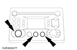
- To access the diagnostic menu, simultaneously PRESS and HOLD the CD/C and NAV buttons and switch the navigation system display module ON.
Follow the instructions shown on the display. - PRESS the right-hand rotary knob, to continue to the next screen.
If a concern is found with the system the diagnostic menu will not proceed any further until the concern is rectified. NOTE:When the concern has been rectified. TEST the system for normal operation. - PRESS the ESC button to exit the diagnostic menu.
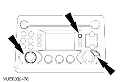
- To access the SERVICE MENU, simultaneously PRESS and HOLD the S4 and MENU buttons and switch the navigation system display module ON.
-
NOTE:Turn the right-hand rotary knob, to highlight the mode required and PRESS the ENTER button to select the mode. SELECT SYSTEMTEST and PRESS the ENTER button. NOTE:When checking the speed sensor it is necessary to drive the vehicle ten meters forwards above 4 km/h (2.5 mph) to make the value change. NOTE:When checking the direction sensor. Select the reverse gear to make the value change. - PRESS ESC to return the SYSTEMTEST menu.
- SELECT INTERNAL TEST and PRESS the ENTER button. CHECK that all of the items shown on the screen are OK.
- PRESS ESC to return to the SYSTEMTEST menu.
Pinpoint Tests | PINPOINT TEST A : NAVIGATION SYSTEM WILL NOT SWITCH ON | | TEST CONDITIONS | DETAILS/RESULTS/ACTIONS | | A1: CHECK FOR VOLTAGE TO NAVIGATION SYSTEM DISPLAY MODULE | | | 1 Disconnect Navigation System Display Module C717. | | | 2 Measure the voltage between the navigation system display module C717 pin 4, circuit 29-MD15 (OG/BK), harness side and ground. | | | Is the voltage greater than 10 volts? Yes No | | A2: CHECK FOR VOLTAGE TO NAVIGATION SYSTEM DISPLAY MODULE | | | 1 Ignition switch in position I. | | | 2 Measure the voltage between the navigation system display module C717 pin 7, circuit 75-MD15 (YE/GN), harness side and ground. | | | Is the voltage greater than 10 volts? Yes No | | A3: CHECK THE CIRCUIT 91-MD15 (BK/GN) TO GROUND | | | 1 Measure the resistance between the navigation system display module C717 pin 8, circuit 91-MD15 (BK/GN), harness side and ground. | | | Is the resistance less than 5 ohms? Yes No REPAIR the circuit. TEST the system for normal operation | | A4: CHECK CENTRAL JUNCTION BOX (CJB) TO NAVIGATION SYSTEM DISPLAY MODULE FOR OPEN | | | 1 Disconnect CJB C813. | | | 2 Measure the resistance between the CJB C813 pin 14, circuit 29-MD15 (OG/BK), harness side and the navigation system display module C483 pin 4, circuit 29-MD15 (OG/BK), harness side. | | | Is the resistance less than 5 ohms? Yes No REPAIR circuit 29-MD15 (OG/BK). TEST the system for normal operation. | | A5: CHECK CJB TO NAVIGATION SYSTEM DISPLAY MODULE FOR OPEN | | | 1 Measure the resistance between the CJB C813 pin 13, circuit 75-MD15 (YE/GN), harness side and the navigation system display module C483 pin 7, circuit 75-MD15 (YE/GN), harness side. | | | Is the resistance less than 5 ohms? Yes INSTALL a new navigation system display module. TEST the system for normal operation. No REPAIR circuit 75-MD15 (YE/GN). TEST the system for normal operation. | | PINPOINT TEST B : NAVIGATION SYSTEM DOES NOT OPERATE CORRECTLY | CAUTION:Make sure that the digital multimeter probes do not come into contact with the other connectors of the antenna cable when taking electrical measurements. Failure to follow this instruction may result in the antenna cable being damaged internally. | | TEST CONDITIONS | DETAILS/RESULTS/ACTIONS | | B1: CHECK ANTENNA CONNECTION | | | 1 CHECK that all connectors of the antenna cable are connected. | | | Are the antenna cable connectors connected? Yes No CONNECT the antenna connector(s). TEST the system for normal operation. | | B2: CHECK ANTENNA CABLE FOR OPEN | | | 1 Disconnect Antenna Cable Connectors. | | | 2 Measure the resistance between the antenna cable upper connector and the antenna cable lower connector. | | | Is the resistance less than 5 ohms? Yes INSTALL a new navigation system display module. TEST the system for normal operation. No INSTALL a new antenna cable. TEST the system for normal operation. | |