| Removal and Installation WARNING:Note the position of the wiring harnesses to aid installation. An incorrectly routed wiring harness could become damaged when the seat is moved. Failure to follow this instruction may result in personal injury. | | -
Remove the front seat.
For additional information, refer to: Front Seat (501-10 Seating, Removal and Installation).
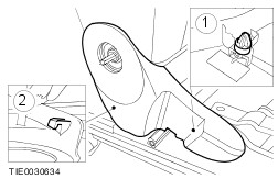
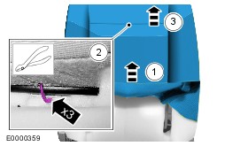
| 2. Remove the components in the order indicated in the following illustration(s) and table(s). 1 - Cushion heater wiring harness electrical connector (if equipped) 2 - Cushion retaining screws 3. To install, reverse the removal procedure. Removal Details Item 4 : Backrest recliner handwheel CAUTION:To avoid damage to the backrest recliner handwheel, even pressure must be applied to the opposite sides of the handwheel. Item 5 : Seat track inner upper trim panel | | -
Remove the seat track inner upper trim panel. - Detach the front retaining clip.
- Detach the rear retaining tang.
| Item 6 : Seat track outer upper trim panel | | -
Remove the seat track outer upper trim panel. - Detach the front retaining clip.
- Detach the rear retaining tang.
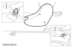
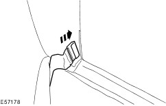
| Item 8 : Head restraint guides | | -
Remove the head restraint guides. - Using a suitable screwdriver, depress the locking tang.
- Pull the guide upwards.
| Item 9 : Backrest release lever | | -
CAUTION:On the left-hand seat, the backrest release lever lower locking tang must be released before the backrest release lever upper locking tang. CAUTION:On the right-hand seat, the backrest release lever upper locking tang must be released before the backrest release lever lower locking tang. NOTE:On the left-hand seat, the backrest release lever upper locking tang is not accessible until the backrest release lever lower locking tang has been released and the backrest release lever repositioned. NOTE:On the right-hand seat, the backrest release lever lower locking tang is not accessible until the backrest release lever upper locking tang has been released and the backrest release lever repositioned. Remove the backrest release lever (left-hand seat shown). - Release the backrest release lever lower locking tang.
- Release the backrest release lever upper locking tang.
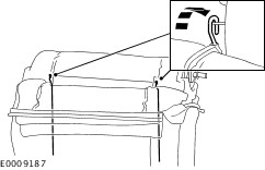
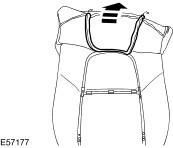
| Item 10 : Backrest cover | | -
Detach the backrest cover from the underside of the backrest. - Detach the retaining strip.
| | | -
Roll the backrest cover up the backrest to gain access to the lower ends of the tensioning rods. | | | -
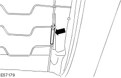
Detach the lower ends of the tensioning rods from the backrest. | | | -
Roll the backrest cover up the backrest to access the upper ends of the tensioning rods. | | | -
Detach the upper ends of the tensioning rods from the backrest. | | | -
Roll the backrest cover up the backrest to access the upper end of the backrest spring frame. | | | -
Detach the backrest cover retaining clip from the backrest spring frame (if equipped). | | | -
Detach the backrest cover from the front of the backrest pad. | | | -
Detach the backrest cover from the backrest pad. - Release the hook loop tape (if equipped).
| | | -
Detach the side air bag deployment sleeve from the backrest frame (if equipped). - Locally detach the side air bag deployment sleeve.
- Detach the retaining strip.
| | | -
Remove the backrest cover. - Detach the retaining strip.
| Item 11 : Backrest cover tensioning rods | | -
Remove the tensioning rods from the backrest cover if a new backrest cover is to be installed. | Installation Details Item 10 : Backrest cover | | -
NOTE:If a replacement backrest cover is to be installed, cut holes for the head restraint guides and backrest release lever. Use the existing backrest cover as a template. NOTE:Use hog ring pliers to close the hog rings. Do not use any other tool. The hog rings must be closed to overlap as illustrated. NOTE:Install new hog rings. | | | -
Push the backrest cover retaining clip through the backrest pad cut-out (if equipped). | | | -
Attach the backrest cover retaining clip to the backrest spring frame (if equipped). | |