| Diagnosis and Testing Refer to Wiring Diagrams Section 501-16, for schematic and connector information. Special Tool(s) | | Terminal Probe Kit 29-011 A | Inspection and Checking NOTE:Before reading out the vehicle-specific data, remake all the electrical connections to the module to be removed, so that communication between the module and WDS is ensured. NOTE:If the generic electronic module (GEM) is changed, the new one must be reinitialised. For this purpose, the vehicle-specific data is read out of the module to be replaced using WDS and is transferred to the new module. REFER to: Module Configuration (418-01 Module Configuration, Diagnosis and Testing), Generic Electronic Module (GEM) - Vehicles Built Up To: 10/2005 (419-10 Multifunction Electronic Modules, Diagnosis and Testing), Generic Electronic Module (GEM) - Vehicles Built From: 10/2005 (419-10 Multifunction Electronic Modules, Diagnosis and Testing). - Verify the customer concern.
- Visually check for any obvious mechanical or electrical damage.
Visual Inspection Chart | Mechanical | Electrical | - Wiper blade(s)
- Rotating shaft – wiper arm
- Washer reservoir
- Hose(s)
- Nozzles
- Check the passenger-side windshield wiper for residue-free wiping in the vicinity of the rain sensor.
- Check the adhesive pad between the rain sensor and the windshield for trapped air.
- Clean wax residues from the windshield in the vicinity of the rain sensor.
- Check the windshield for damage/cracks in the vicinity of the rain sensor.
- Check that the rain sensor retaining frame is correctly attached to the windshield.
| - Fuse(s)
- Connectors
- Wiring harness
- Washer pump
- Front/rear window wiper motor
| - Resolve any obvious causes or concerns found during the visual inspection before carrying out any further tests.
- If the concern is not visually evident, refer to the Symptom Chart.
Symptom Chart Symptom Chart | Symptom | Possible Sources | Action | | No communication with the generic electronic module (GEM) | * Data bus (ISO 9141) * Generic Electronic Module (GEM) | * REFER to: (418-00 Module Communications Network) Communications Network - Vehicles Built Up To: 10/2005 (Diagnosis and Testing), Communications Network - Vehicles Built From: 10/2005 (Diagnosis and Testing). | | Wipers inoperative | * Fuse * Circuit(s) * Wash/wipe system switch * Windshield wiper motor * Rear wiper motor * Generic Electronic Module (GEM) * Central junction box (CJB) | * | | Brief wipe is inoperative (slow wipe OK) | * Wash/wipe switch | * RENEW the wash/wipe switch. CHECK the operation of the system. | | The rear window wiper is inoperative when the front wiper is switched on and reverse gear engaged (normal wipe function OK and the reversing lamps illuminate). | * Circuit(s) * Generic Electronic Module (GEM) | * LOCATE and RECTIFY the break in circuit 15S-LG28 (GN/WH) between soldered connection S32 and the generic electronic module using the Wiring Diagrams. CHECK the operation of the system. If the concern persists, CHECK the GEM using WDS, RENEW if necessary. CHECK the operation of the system. | | Wipers permanently switched on | * Circuit(s) * Wash/wipe system switch * Windshield wiper motor * Rear wiper motor * Generic Electronic Module (GEM) | * | | Slow/fast wipe not working | * Circuit(s) * Wash/wipe system switch * Windshield wiper motor | * | | Intermittent wipe mode of windshield wiper inoperative, vehicles with and without rain sensor (fast/slow wipe OK) | * Circuit(s) * Wash/wipe switch * Generic Electronic Module (GEM) * Rain sensor | * | | Wash/wipe function inoperative | * Circuit(s) * Wash/wipe system switch * Generic Electronic Module (GEM) | * | | Windshield wipers do not return to park position after switching off | * Circuit(s) * Wash/wipe system switch * Windshield wiper motor * Rear wiper motor * Generic Electronic Module (GEM) | * | | Washer pump motor inoperative | * Circuit(s) * Washer pump motor * Wash/wipe system switch | * | System Check NOTE:Use a digital multimeter for all electrical measurements. | PINPOINT TEST A : WIPERS INOPERATIVE | | TEST CONDITIONS | DETAILS/RESULTS/ACTIONS | | A1: DETERMINE THE FAULT CONDITION | | | 1 Ignition switch in position II. | | | 2 SWITCH ON front wiper. | | | 3 SWITCH ON rear window wiper. | | | Are both wipers inoperative? Yes No - Rear window wiper inoperative: GO to A5. | | A2: CHECK FUSE F46 (20 A) (CJB). | | | 1 Ignition switch in position 0. | | | 2 Disconnect fuse F46 (20 A) (CJB). | | | 3 CHECK fuse F46 (20 A) (CJB). | | | Is the fuse OK? Yes No RENEW fuse F46 (20 A) (CJB) and CHECK the operation of the system. If the fuse blows again, LOCATE and RECTIFY the short to ground using the Wiring Diagrams. CHECK the operation of the system. | | A3: CHECK THE VOLTAGE SUPPLY TO FUSE F46 (20A) (CJB) FOR OPEN CIRCUIT | | | 1 Ignition switch in position 0. | | | 2 Connect fuse F46 (20 A) (CJB). | | | 3 Ignition switch in position II. | | | 4 Measure the voltage between fuse F46 (20 A) (CJB) and ground. | | | Is battery voltage measured? Yes No CHECK and if necessary INSTALL A NEW CJB. CHECK the operation of the system. | | A4: CHECK THE VOLTAGE SUPPLY TO THE WASH/WIPE SYSTEM SWITCH FOR OPEN CIRCUIT | | | 1 Ignition switch in position 0. | | | 2 Disconnect wash/wipe system switch from connector C361. | | | 3 Ignition switch in position II. | | | 4 Measure voltage between wash/wipe switch, connector C361, pin 6, circuit 15-KA19 (GN/OG)/15-KA13 (GN/OG), wiring harness side and ground. | | | Does the meter display battery voltage? Yes RENEW the wash/wipe system switch. CHECK the operation of the system. No LOCATE and RECTIFY the break in the circuit between fuse F46 (CJB) and the wash/wipe system switch using the Wiring Diagrams. CHECK the operation of the system. | | A5: CHECK FUSE F47 (10 A) (CJB). | | | 1 Ignition switch in position 0. | | | 2 Disconnect fuse F47 (10 A) (CJB). | | | 3 CHECK fuse F47 (10 A) (CJB). | | | Is the fuse OK? Yes No RENEW fuse F47 (10 A) (CJB) and CHECK the operation of the system. If the fuse blows again, LOCATE and RECTIFY the short to ground using the Wiring Diagrams. CHECK the operation of the system. | | A6: CHECK THE VOLTAGE SUPPLY TO FUSE F47 (10A) (CJB) FOR OPEN CIRCUIT | | | 1 Ignition switch in position 0. | | | 2 Connect fuse F47 (10 A) (CJB). | | | 3 Ignition switch in position II. | | | 4 Measure the voltage between fuse F47 (10 A) (CJB) and ground. | | | Does the meter display battery voltage? Yes No CHECK and if necessary INSTALL A NEW CJB. CHECK the operation of the system. | | A7: CHECK THE WASH/WIPE SYSTEM SWITCH | | | 1 Ignition switch in position 0. | | | 2 Disconnect wash/wipe system switch from connector C361. | | | 3 CHECK the wash/wipe system switch according to the component check at the end of this section. - Perform the check on the rear wiper circuit at the wash/wipe system switch.
| | | Is the wash/wipe system switch OK? Yes No RENEW the wash/wipe system switch. CHECK the operation of the system. | | A8: CHECK VOLTAGE AT THE REAR WINDOW WIPER MOTOR | NOTE:The minimum measurement duration is 20 seconds. | | | 1 Ignition switch in position 0. | | | 2 Disconnect rear window wiper motor from connector C562. | | | 3 Ignition switch in position II. | | | 4 SWITCH ON rear window wiper. | | | 5 Measure the voltage between: - Vehicles without anti-theft alarm system: Rear window wiper motor, connector C562, pin 1, circuit 15S-KA28 (GN/BU), wiring harness side and ground.
- Vehicles with anti-theft alarm system: Rear window wiper motor, connector C562, pin 1, circuit 31-KA28S (BK), wiring harness side and ground.
| | | Is battery voltage measured approximately every 10 seconds? Yes No | | A9: CHECK THE GROUND CONNECTION OF THE REAR WIPER MOTOR FOR OPEN CIRCUIT | | | 1 Ignition switch in position 0. | | | 2 Measure the resistance between the rear wiper motor, connector C562, pin 3, circuit 31-KA28 (BK), wiring harness side and ground. | | | Is a resistance of less than 2 ohms registered? Yes RENEW the wiper motor. CHECK the operation of the system. No LOCATE and RECTIFY the break in the circuit between the wiper motor and soldered connection S201 using the wiring diagrams. CHECK the operation of the system. | | A10: CHECK CIRCUIT 15S-KA28 (GN/BU) BETWEEN THE GENERIC ELECTRONIC MODULE (GEM) AND THE REAR WIPER MOTOR FOR OPEN CIRCUIT | | | 1 Ignition switch in position 0. | | | 2 Disconnect Generic Electronic Module (GEM). - Vehicles built before 08/2005: from connector C316
- Vehicles built from 08/2005: from connector C319
| | | 3 Measure the resistance between the generic electronic module (GEM): - Vehicles built before 08/2005 without anti-theft alarm system: Connector C316, pin 5, circuit 15S-KA28 (GN/BU) and rear wiper motor, connector C562, pin 1, circuit 15S-KA28 (GN/BU), wiring harness side.
- Vehicles built before 08/2005 with anti-theft alarm system: Connector C316, pin 5, circuit 15S-KA28 (GN/BU) and rear wiper motor, connector C562, pin 1, circuit 31-KA28S (BK), wiring harness side.
- Vehicles built from 08/2005 without anti-theft alarm system: Connector C319, pin 5, circuit 15S-KA28 (GN/BU) and rear wiper motor, connector C562, pin 1, circuit 15S-KA28 (GN/BU), wiring harness side.
- Vehicles built from 08/2005 with anti-theft alarm system: Connector C319, pin 5, circuit 15S-KA28 (GN/BU) and rear wiper motor, connector C562, pin 1, circuit 31-KA28S (BK), wiring harness side.
| | | Is a resistance of less than 2 ohms registered? Yes No LOCATE and RECTIFY the break in the circuit between the generic electronic module (GEM) and the rear wiper motor using the Wiring Diagrams. CHECK the operation of the system. | | A11: CHECK VOLTAGE SUPPLY TO GENERIC ELECTRONIC MODULE (GEM) FOR OPEN CIRCUIT | | | 1 Ignition switch in position 0. | | | 2 Connect Wash/wipe system switch to connector C361. | | | 3 Disconnect Generic electronic module (GEM) from connector C320. | | | 4 Ignition switch in position II. | | | 5 SWITCH ON rear window wiper. | | | 6 Measure the voltage between the generic electronic module (GEM), connector C320, pin 20, circuit 32-KA35A (WH/RD), wiring harness side and ground. | | | Does the meter display battery voltage? Yes No LOCATE and RECTIFY the break in the circuit between the wash/wipe system switch and generic electronic module (GEM) using the Wiring Diagrams. CHECK the operation of the system. | | A12: CHECK VOLTAGE SUPPLY TO GENERIC ELECTRONIC MODULE (GEM) FOR OPEN CIRCUIT | | | 1 Ignition switch in position 0. | | | 2 Disconnect Generic electronic module (GEM) from connector C319. | | | 3 Ignition switch in position II. | | | 4 Measure the voltage between the generic electronic module (GEM): - Vehicles built before 08/2005: connector C319, pin 2, circuit 15-KA30 (GN/BU), wiring harness side and ground.
- Vehicles built from 08/2005: connector C319, pin 7, circuit 15-KA30 (GN/BU), wiring harness side and ground.
| | | Is battery voltage measured? Yes No LOCATE and RECTIFY the break in the circuit between fuse F47 (CJB) and the generic electronic module (GEM) using the Wiring Diagrams. CHECK the operation of the system. | | A13: CHECK VOLTAGE SUPPLY TO GENERIC ELECTRONIC MODULE (GEM) FOR OPEN CIRCUIT | | | 1 Measure the voltage between the generic electronic module (GEM), connector C319, pin 10, circuit 15-DK20 (GN/OG), wiring harness side and ground. | | | Is battery voltage measured? Yes No LOCATE and RECTIFY the break in the circuit between soldered connection S3 and the generic electronic module (GEM) using the Wiring Diagrams. CHECK the operation of the system. | | A14: CHECK GROUND CONNECTION OF GENERIC ELECTRONIC MODULE (GEM) FOR OPEN CIRCUIT | | | 1 Ignition switch in position 0. | | | 2 Measure the resistance between the generic electronic module (GEM), connector C320, pin 2, circuit 91-DK20 (BK/RD), wiring harness side and ground. | | | Is a resistance of less than 2 ohms registered? Yes No - Vehicles built before 08/2005: LOCATE and RECTIFY the break in the circuit between the generic electronic module (GEM) and ground connection G14 using the Wiring Diagrams. CHECK the operation of the system. - Vehicles built from 08/2005: LOCATE and RECTIFY the break in the circuit between the generic electronic module (GEM) and soldered connection S264 using the Wiring Diagrams. CHECK the operation of the system. | | A15: CHECK GROUND CONNECTION OF GENERIC ELECTRONIC MODULE (GEM) FOR OPEN CIRCUIT | | | 1 Disconnect Generic Electronic Module (GEM). - Vehicles built before 08/2005: from connector C316
- Vehicles built from 08/2005: from connector C318
| | | 2 Measure the resistance between the generic electronic module (GEM): - Vehicles built before 08/2005: Connector C316, pin 2, circuit 31-DK20 (BK), wiring harness side and ground.
- Vehicles built from 08/2005: Connector C318, pin 3, circuit 31-DK20 (BK), wiring harness side and ground.
| | | Is a resistance of less than 2 ohms registered? Yes RENEW the generic electronic module (GEM). CHECK the operation of the system. No LOCATE and RECTIFY the break in the circuit between the generic electronic module (GEM) and soldered connection S15 using the Wiring Diagrams. CHECK the operation of the system. | | A16: CHECK THE WASH/WIPE SYSTEM SWITCH | | | 1 Ignition switch in position 0. | | | 2 Disconnect wash/wipe system switch from connector C361. | | | 3 CHECK the wash/wipe system switch according to the component check at the end of this section. - Perform the check on the fast and slow front wipe circuit at the wash/wipe system switch.
| | | Is the wash/wipe switch OK? Yes No RENEW the wash/wipe system switch. CHECK the operation of the system. | | A17: CHECK THE GROUND CONNECTION OF THE FRONT WIPER MOTOR FOR OPEN CIRCUIT | | | 1 Disconnect front wiper motor from connector C313. | | | 2 Measure the resistance between: - LHD: front wiper motor, connector C313, pin 2, circuit 31-KA8 (BK), wiring harness side and ground.
- RHD: front wiper motor, connector C313, pin 4, circuit 31-KA8 (BK), wiring harness side and ground.
| | | Is a resistance of less than 2 ohms registered? Yes RENEW the wiper motor. CHECK the operation of the system. No LOCATE and RECTIFY the break in the circuit between the wiper motor and soldered connection S15 using the wiring diagrams. CHECK the operation of the system. | | PINPOINT TEST B : WIPERS PERMANENTLY SWITCHED ON | | TEST CONDITIONS | DETAILS/RESULTS/ACTIONS | | B1: DETERMINE THE FAULT CONDITION | | | 1 Ignition switch in position 0. | | | 2 Disconnect wash/wipe system switch from connector C361. | | | 3 Ignition switch in position II. | | | 4 CHECK the front and rear wipers. | | | Does the rear window wiper motor run continuously in intermittent wipe mode? Yes No - The rear window wiper motor runs continuously (not in intermittent mode) when the front wiper is switched off: GO to B10. - The rear window wiper motor runs continuously (not in intermittent mode) when the front wiper is switched on:
REFER to: Reversing Lamps - Vehicles Built Up To: 10/2005 (417-01 Exterior Lighting, Diagnosis and Testing).
- The front wiper motor is running continually at the slow wipe speed: GO to B2. - The front wiper motor is running continually at the fast wipe speed: GO to B7. - No malfunction detected: The front wiper motor is running continuously at slow wipe speed: GO to B3. - No malfunction detected: The front wiper motor is running continuously at fast wipe speed: RENEW the wash/wipe switch. CHECK the operation of the system. - No malfunction detected: The front wiper motor is running continually in intermittent wipe mode: GO to B5. - No malfunction detected: The rear wiper motor is running continually in intermittent wipe mode: RENEW the wash/wipe switch. CHECK the operation of the system. | | B2: CHECK THE FRONT WIPER MOTOR | | | 1 Ignition switch in position 0. | | | 2 Disconnect windshield wiper motor from connector C313. | | | 3 Ignition switch in position II. | | | 4 Measure the voltage between: - LHD: front wiper motor, connector C313, pin 1, circuit 15S-KA10 (GN/BK), wiring harness side and ground.
- RHD: front wiper motor, connector C313, pin 5, circuit 15S-KA10 (GN/BK), wiring harness side and ground.
| | | Does the meter display battery voltage? Yes LOCATE and RECTIFY the short to battery voltage in the circuit between the wash/wipe system switch and wiper motor using the Wiring Diagrams. CHECK the operation of the system. No RENEW the windshield wiper motor. CHECK the operation of the system. | | B3: CHECK THE WASH/WIPE SYSTEM SWITCH. | | | 1 Measure the voltage between the wash/wipe system switch, connector C361, pin 7, circuit 15S-KA19 (GN/OG), wiring harness side and ground. | | | Does the meter display battery voltage? Yes No RENEW the wash/wipe system switch. CHECK the operation of the system. | | B4: CHECK CIRCUIT 15S-KA19 (GN/OG) BETWEEN THE WASH/WIPE SWITCH AND THE GENERIC ELECTRONIC MODULE (GEM) FOR SHORT CIRCUIT TO BATTERY VOLTAGE | | | 1 Ignition switch in position 0. | | | 2 Disconnect Generic electronic module (GEM) from connector C320. | | | 3 Ignition switch in position II. | | | 4 Measure the voltage between the wash/wipe system switch, connector C361, pin 7, circuit 15S-KA19 (GN/OG), wiring harness side and ground. | | | Is battery voltage measured? Yes LOCATE and RECTIFY the short to battery voltage in the circuit between the wash/wipe system switch and generic electronic module (GEM) using the Wiring Diagrams. CHECK the operation of the system. No RENEW the generic electronic module (GEM). CHECK the operation of the system. | | B5: CHECK THE WASH/WIPE SYSTEM SWITCH. | | | 1 Measure the voltage between the wash/wipe switch, connector C361, pin 10, circuit 15S-KA14 (GN/BK), wiring harness side and ground. | | | Does the meter display battery voltage? Yes No RENEW the wash/wipe switch. CHECK the operation of the system. | | B6: CHECK CIRCUIT 15S-KA14 (GN/BK) BETWEEN THE WASH/WIPE SWITCH AND THE GENERIC ELECTRONIC MODULE (GEM) FOR SHORT CIRCUIT TO BATTERY VOLTAGE | | | 1 Ignition switch in position 0. | | | 2 Disconnect Generic electronic module (GEM) from connector C320. | | | 3 Ignition switch in position II. | | | 4 Measure the voltage between the wash/wipe switch, connector C361, pin 10, circuit 15S-KA14 (GN/BK), wiring harness side and ground. | | | Does the meter display battery voltage? Yes LOCATE and RECTIFY the short to battery voltage in the circuit between the wash/wipe system switch and generic electronic module (GEM) using the Wiring Diagrams. CHECK the operation of the system. No RENEW the generic electronic module (GEM). CHECK the operation of the system. | | B7: NARROW DOWN THE FAULT CONDITION | | | 1 Measure the voltage between: - LHD: front wiper motor, connector C313, pin 5, circuit 15S-KA11 (GN/OG), wiring harness side and ground.
- RHD: front wiper motor, connector C313, pin 1, circuit 15S-KA11 (GN/OG), wiring harness side and ground.
| | | Does the meter display battery voltage? Yes - Vehicles without rain sensor: LOCATE and RECTIFY the short to battery voltage in the circuit between the wash/wipe system switch and the front wiper motor using the Wiring Diagrams. CHECK the operation of the system. No RENEW the front wiper motor. CHECK the operation of the system. | | B8: CHECK THE GENERIC ELECTRONIC MODULE (GEM). | | | 1 Ignition switch in position 0. | | | 2 Disconnect Generic electronic module (GEM) from connector C319. | | | 3 Ignition switch in position II. | | | 4 Measure the voltage between: - LHD: front wiper motor, connector C313, pin 5, circuit 15S-KA11 (GN/OG), wiring harness side and ground.
- RHD: front wiper motor, connector C313, pin 1, circuit 15S-KA11 (GN/OG), wiring harness side and ground.
| | | Is battery voltage measured? Yes LOCATE and RECTIFY the short to battery voltage in the circuits connected to soldered connection S21 using the Wiring Diagrams. CHECK the operation of the system. No RENEW the generic electronic module (GEM). CHECK the operation of the system. | | B9: CHECK CIRCUIT 32-KA35A (WH/RD) BETWEEN THE WASH/WIPE SWITCH AND THE GENERIC ELECTRONIC MODULE (GEM) FOR SHORT CIRCUIT TO BATTERY VOLTAGE | | | 1 Ignition switch in position 0. | | | 2 Disconnect Generic electronic module (GEM) from connector C320. | | | 3 Ignition switch in position II. | | | 4 Measure the voltage between the generic electronic module (GEM), connector C320, pin 20, circuit 32-KA35A (WH/RD), wiring harness side and ground. | | | Does the meter display battery voltage? Yes LOCATE and RECTIFY the short to battery voltage in the circuit between the wash/wipe system switch and generic electronic module (GEM) using the Wiring Diagrams. CHECK the operation of the system. No RENEW the generic electronic module (GEM). CHECK the operation of the system. | | B10: CHECK THE REAR WIPER MOTOR | | | 1 Ignition switch in position 0. | | | 2 Disconnect rear window wiper motor from connector C562. | | | 3 Ignition switch in position II. | | | 4 Measure the voltage between: - Vehicles without anti-theft alarm system: Rear wiper motor, connector C562, pin 1, circuit 15S-KA28 (GN/BU), wiring harness side and ground.
- Vehicles with anti-theft alarm system: Rear wiper motor, connector C562, pin 1, circuit 31-KA28S (BK), wiring harness side and ground.
| | | Does the meter display battery voltage? Yes No INSTALL a new rear wiper motor. CHECK the operation of the system. | | B11: CHECK CIRCUIT 15S-KA28 (GN/BU) BETWEEN THE GENERIC ELECTRONIC MODULE (GEM) AND THE REAR WIPER MOTOR FOR SHORT CIRCUIT TO BATTERY VOLTAGE | | | 1 Ignition switch in position 0. | | | 2 Disconnect Generic Electronic Module (GEM). - Vehicles built before 08/2005: from connector C316
- Vehicles built from 08/2005: from connector C319
| | | 3 Ignition switch in position II. | | | 4 Measure the voltage between: - Vehicles without anti-theft alarm system: Rear wiper motor, connector C562, pin 1, circuit 15S-KA28 (GN/BU), wiring harness side and ground.
- Vehicles with anti-theft alarm system: Rear wiper motor, connector C562, pin 1, circuit 31-KA28S (BK), wiring harness side and ground.
| | | Does the meter display battery voltage? Yes LOCATE and RECTIFY the short to battery voltage in the circuit between the generic electronic module (GEM) and rear wiper motor using the Wiring Diagrams. CHECK the operation of the system. No RENEW the generic electronic module (GEM). CHECK the operation of the system. | | PINPOINT TEST C : SLOW/FAST WIPE NOT WORKING. | | TEST CONDITIONS | DETAILS/RESULTS/ACTIONS | | C1: DETERMINE THE FAULT CONDITION | | | 1 Ignition switch in position II. | | | 2 SWITCH ON slow and fast wipe speed in succession. | | | 3 CHECK front wipers. | | | Do the wipers operate at fast speed? Yes No | | C2: CHECK FRONT WIPER MOTOR (FAST WIPE SPEED) | | | 1 Ignition switch in position 0. | | | 2 Disconnect windshield wiper motor from connector C313. | | | 3 Ignition switch in position II. | | | 4 SWITCH ON fast wipe speed. | | | 5 Measure the voltage between: - LHD: front wiper motor, connector C313, pin 5, circuit 15S-KA11 (GN/OG), wiring harness side and ground.
- RHD: front wiper motor, connector C313, pin 1, circuit 15S-KA11 (GN/OG), wiring harness side and ground.
| | | Does the meter display battery voltage? Yes RENEW the windshield wiper motor. CHECK the operation of the system. No | | C3: CHECK THE WASH/WIPE SYSTEM SWITCH | | | 1 Ignition switch in position 0. | | | 2 Disconnect wash/wipe system switch from connector C361. | | | 3 CHECK the wash/wipe system switch according to the component check at the end of this section. - Perform the check on the fast front wipe speed circuit at the wash/wipe system switch.
| | | Is the wash/wipe system switch OK? Yes LOCATE and RECTIFY the break in circuit 15S-KA11 (GN/OG) between the wash/wipe system switch and the front wiper motor using the Wiring Diagrams. CHECK the operation of the system. No RENEW the wash/wipe system switch. CHECK the operation of the system. | | C4: CHECK FRONT WIPER MOTOR (SLOW WIPE SPEED) | | | 1 Ignition switch in position 0. | | | 2 Disconnect windshield wiper motor from connector C313. | | | 3 Ignition switch in position II. | | | 4 SWITCH ON slow wipe speed. | | | 5 Measure the voltage between: - LHD: front wiper motor, connector C313, pin 1, circuit 15S-KA10 (GN/BK), wiring harness side and ground.
- RHD: front wiper motor, connector C313, pin 5, circuit 15S-KA10 (GN/BK), wiring harness side and ground.
| | | Does the meter display battery voltage? Yes RENEW the front wiper motor. CHECK the operation of the system. No | | C5: CHECK THE WASH/WIPE SYSTEM SWITCH | | | 1 Ignition switch in position 0. | | | 2 Disconnect wash/wipe system switch from connector C361. | | | 3 CHECK the wash/wipe system switch according to the component check at the end of this section. - Perform the check on the slow front wipe speed circuit at the wash/wipe system switch.
| | | Is the wash/wipe system switch OK? Yes LOCATE and RECTIFY the break in circuit 15S-KA10 (GN/BK) between the wash/wipe system switch and the front wiper motor using the Wiring Diagrams. CHECK the operation of the system. No RENEW the wash/wipe system switch. CHECK the operation of the system. | | PINPOINT TEST D : INTERMITTENT WIPE MODE OF FRONT WIPER INOPERATIVE, VEHICLES WITH AND WITHOUT RAIN SENSOR (FAST/SLOW WIPE OK) | | TEST CONDITIONS | DETAILS/RESULTS/ACTIONS | | D1: NARROW DOWN THE POSSIBLE CAUSES FOR THE FAULT | | | 1 Ignition switch in position II. | | | 2 SWITCH slow wipe ON and OFF. | | | 3 CHECK front wipers. | | | Do the wipers return to the park position after switching them off? Yes No | | D2: CHECK THE EQUIPMENT LEVEL | | | 1 Check the equipment level | | | Is the vehicle equipped with a rain sensor? Yes No | | D3: NARROW DOWN THE FAULT CONDITION | | | 1 SWITCH ON intermittent mode at the wash/wipe system switch. | | | 2 Vehicles built from 08/2005: Adjust the wipe cycle at the wash/wipe system switch. | | | 3 CHECK front wipers. | | | Is intermittent mode of front wipers inoperative? Yes No The front wiper motor performs a different wipe cycle than the one set with the wash/wipe switch: GO to D10. | | D4: CHECK THE WASH/WIPE SYSTEM SWITCH. | | | 1 Ignition switch in position 0. | | | 2 Disconnect wash/wipe system switch from connector C361. | | | 3 CHECK the wash/wipe system switch according to the component check at the end of this section. - Perform the check on the intermittent front wipe circuit at the wash/wipe system switch.
| | | Is the wash/wipe switch OK? Yes - Vehicles without rain sensor: GO to D5. No RENEW the wash/wipe switch. CHECK the operation of the system. | | D5: CHECK CIRCUIT 15S-KA14A (GN/BK) BETWEEN THE WASH/WIPE SWITCH AND THE GENERIC ELECTRONIC MODULE (GEM) FOR OPEN CIRCUIT | | | 1 Connect Wash/wipe system switch to connector C361. | | | 2 Disconnect Generic electronic module (GEM) from connector C320. | | | 3 Ignition switch in position II. | | | 4 SWITCH ON intermittent wiping. | | | 5 Measure the voltage between the generic electronic module (GEM), connector C320, pin 19, circuit 15S-KA14A (GN/BK), wiring harness side and ground. | | | Does the meter display battery voltage? Yes No LOCATE and RECTIFY the break in the circuit between the wash/wipe system switch and generic electronic module (GEM) using the Wiring Diagrams. CHECK the operation of the system. | | D6: CHECK VOLTAGE SUPPLY TO GENERIC ELECTRONIC MODULE (GEM) FOR OPEN CIRCUIT | | | 1 Ignition switch in position 0. | | | 2 Disconnect Vehicles built before 08/2005: Generic electronic module (GEM) from connector C319. | | | 3 Ignition switch in position II. | | | 4 Measure the voltage between the generic electronic module (GEM): - Vehicles built before 08/2005: connector C319, pin 3, circuit 15-KA13 (GN/YE), wiring harness side and ground.
- Vehicles built from 08/2005: connector C320, pin 5, circuit 15-KA13 (GN/YE), wiring harness side and ground.
| | | Is battery voltage measured? Yes No - Vehicles built before 08/2005: LOCATE and RECTIFY the break in the circuit between soldered connection S22 and generic electronic module (GEM) using the Wiring Diagrams. CHECK the operation of the system. - Vehicles built from 08/2005: LOCATE and RECTIFY the break in the circuit between the wash/wipe system switch pin 6 and the generic electronic module (GEM) using the Wiring Diagrams. CHECK the operation of the system. | | D7: CHECK VOLTAGE SUPPLY TO GENERIC ELECTRONIC MODULE (GEM) FOR OPEN CIRCUIT | | | 1 Measure the voltage between the generic electronic module (GEM), connector C319, pin 10, circuit 15-DK20 (GN/OG), wiring harness side and ground. | | | Does the meter display battery voltage? Yes No LOCATE and RECTIFY the break in the circuit between soldered connection S3 and the generic electronic module (GEM) using the Wiring Diagrams. CHECK the operation of the system. | | D8: CHECK GROUND CONNECTION OF GENERIC ELECTRONIC MODULE (GEM) FOR OPEN CIRCUIT | | | 1 Ignition switch in position 0. | | | 2 Measure the resistance between the generic electronic module (GEM), connector C320, pin 2, circuit 91-DK20 (BK/RD), wiring harness side and ground. | | | Is a resistance of less than 2 ohms registered? Yes No - Vehicles built before 08/2005: LOCATE and RECTIFY the break in the circuit between the generic electronic module (GEM) and ground connection G14 using the Wiring Diagrams. CHECK the operation of the system. - Vehicles built from 08/2005: LOCATE and RECTIFY the break in the circuit between the generic electronic module (GEM) and soldered connection S264 using the Wiring Diagrams. CHECK the operation of the system. | | D9: CHECK GROUND CONNECTION OF GENERIC ELECTRONIC MODULE (GEM) FOR OPEN CIRCUIT | | | 1 Disconnect Generic Electronic Module (GEM). - Vehicles built before 08/2005: from connector C316
- Vehicles built from 08/2005: from connector C318
| | | 2 Measure the resistance between the generic electronic module (GEM), - Vehicles built before 08/2005: Connector C316, pin 2, circuit 31-DK20 (BK), wiring harness side and ground.
- Vehicles built from 08/2005: Connector C318, pin 3, circuit 31-DK20 (BK), wiring harness side and ground.
| | | Is a resistance of less than 2 ohms registered? Yes RENEW the generic electronic module (GEM). CHECK the operation of the system. No LOCATE and RECTIFY the break in the circuit between the generic electronic module (GEM) and soldered connection S15 using the Wiring Diagrams. CHECK the operation of the system. | | D10: CHECK THE WASH/WIPE SYSTEM SWITCH. | | | 1 Ignition switch in position 0. | | | 2 Disconnect wash/wipe system switch from connector C361. | | | 3 CHECK the wash/wipe system switch according to the component check at the end of this section. - Perform the check on the variable wipe times circuit at the wash/wipe system switch.
| | | Is the wash/wipe switch OK? Yes No RENEW the wash/wipe switch. CHECK the operation of the system. | | D11: CHECK CIRCUIT 15S-KA18 (GN/YE) BETWEEN THE WASH/WIPE SWITCH AND THE GENERIC ELECTRONIC MODULE (GEM) FOR OPEN CIRCUIT | | | 1 Disconnect Generic electronic module (GEM) from connector C320. | | | 2 Measure the resistance between the wash/wipe system switch, connector C361, pin 1, circuit 15S-KA18 (GN/YE), wiring harness side and the generic electronic module (GEM), connector C320, pin 10, circuit 15S-KA18 (GN/YE), wiring harness side. | | | Is a resistance of less than 2 ohms registered? Yes INSTALL a new GEM. CHECK the operation of the system. No LOCATE and RECTIFY the break in the circuit between the wash/wipe system switch and generic electronic module (GEM) using the Wiring Diagrams. CHECK the operation of the system. | | D12: DETERMINE THE FAULT CONDITION | | | 1 SWITCH ON automatic mode at the wash/wipe system switch. | | | Does the front wiper motor perform a wipe cycle every six seconds? Yes No - Auto function sensitivity cannot be ADJUSTED: GO to D10. | | D13: NARROW DOWN THE FAULT CONDITION | NOTE:Wet the windshield several times with a small amount of water in the vicinity of the rain sensor, in order to check whether the front wiper motor runs at slow wipe speed. | NOTE:Wet the windshield several times with a large amount of water in the vicinity of the rain sensor, in order to check whether the front wiper motor runs at fast wipe speed. | | | 1 Ignition switch in position 0. | | | 2 Connect Wash/wipe system switch to connector C361. | | | 3 Ignition switch in position II. | | | 4 SWITCH ON automatic mode at the wash/wipe system switch. | | | Does the front wiper motor run at slow wipe speed? Yes - Front wiper motor is not running: GO to D5. - The front wiper motor does not run at fast wipe speed: GO to D14. No The front wiper motor does not run at slow wipe speed: RENEW the generic electronic module (GEM). CHECK the operation of the system. | | D14: CHECK THE VOLTAGE AT THE GENERIC ELECTRONIC MODULE (GEM) (FAST WIPE SPEED) | | | 1 Ignition switch in position 0. | | | 2 Disconnect Generic electronic module (GEM) from connector C319. | | | 3 Ignition switch in position II. | | | 4 SWITCH ON fast wipe speed. | | | 5 Measure the voltage between the generic electronic module (GEM), connector C319, pin 3, circuit 15S-KA11B (GN/OG), wiring harness side and ground. | | | Is battery voltage measured? Yes RENEW the generic electronic module (GEM). CHECK the operation of the system. No LOCATE and RECTIFY the break in the circuit between soldered connection S23 and the generic electronic module (GEM) using the Wiring Diagrams. CHECK the operation of the system. | | D15: CHECK VOLTAGE SUPPLY TO RAIN SENSOR FOR OPEN CIRCUIT | | | 1 Ignition switch in position 0. | | | 2 Disconnect Rain sensor from connector C754. | | | 3 Ignition switch in position II. | | | 4 Measure the voltage between the rain sensor, connector C754, pin 1, circuit 15-LE55 (GN/OG), wiring harness side and ground. | | | Is battery voltage measured? Yes No LOCATE and RECTIFY the break in the circuit between soldered connection S3 and the rain sensor using the Wiring Diagrams. CHECK the operation of the system. | | D16: CHECK THE GROUND CONNECTION OF THE RAIN SENSOR FOR OPEN CIRCUIT | | | 1 Ignition switch in position 0. | | | 2 Measure the resistance between the rain sensor, connector C754, pin 2, circuit 31-LE55 (BK), wiring harness side and ground. | | | Is a resistance of less than 2 ohms registered? Yes No LOCATE and RECTIFY the break in the circuit between the rain sensor and soldered connection S264 using the Wiring Diagrams. CHECK the operation of the system. | | D17: CHECK SIGNAL CABLE OF RAIN SENSOR FOR SHORT TO BATTERY VOLTAGE | | | 1 Disconnect Generic electronic module (GEM) from connector C316. | | | 2 Ignition switch in position II. | | | 3 Measure the voltage between the rain sensor, connector C754, pin 3, circuit 8-LE55 (WH/BK), wiring harness side and ground. | | | Is battery voltage measured? Yes LOCATE and RECTIFY the short to battery voltage in the circuit between the generic electronic module (GEM) and the rain sensor using the Wiring Diagrams. CHECK the operation of the system. No | | D18: CHECK SIGNAL CABLE OF RAIN SENSOR FOR SHORT TO GROUND | | | 1 Ignition switch in position 0. | | | 2 Measure the resistance between the rain sensor, connector C754, pin 3, circuit 8-LE55 (WH/BK), wiring harness side and ground. | | | Is a resistance of more than 10,000 ohms measured? Yes No LOCATE and RECTIFY the short to ground in the circuit between the generic electronic module (GEM) and the rain sensor using the Wiring Diagrams. CHECK the operation of the system. | | D19: CHECK SIGNAL CABLE OF RAIN SENSOR FOR OPEN CIRCUIT | | | 1 Measure the resistance between the generic electronic module (GEM), connector C316, pin 2, circuit 8-LE55 (WH/BK), wiring harness side and the rain sensor, connector C754, pin 3, circuit 8-LE55 (WH/BK), wiring harness side. | | | Is a resistance of less than 2 ohms registered? Yes RENEW the rain sensor. CHECK the operation of the system. If the concern persists, RENEW the generic electronic module (GEM). CHECK the operation of the system. No LOCATE and RECTIFY the break in the circuit between the generic electronic module (GEM) and the rain sensor using the Wiring Diagrams. CHECK the operation of the system. | | PINPOINT TEST E : WASH/WIPE FUNCTION INOPERATIVE | | TEST CONDITIONS | DETAILS/RESULTS/ACTIONS | | E1: DETERMINE THE FAULT CONDITION | | | 1 Ignition switch in position II. | | | 2 SWITCH ON the front and rear wash/wipe functions in turn. | | | 3 CHECK the front and rear wash/wipe functions. | | | Is the wash/wipe function inoperative at the front and rear? Yes No - Windshield wipe function inoperative (washer OK): GO to E2. - Rear wipe function inoperative (washer OK): GO to E3. | | E2: CHECK THE VOLTAGE AT THE GENERIC ELECTRONIC MODULE (GEM) | | | 1 Ignition switch in position 0. | | | 2 Disconnect Generic electronic module (GEM) from connector C320. | | | 3 Ignition switch in position II. | | | 4 SWITCH OFF wiper. | | | 5 Measure the voltage between the generic electronic module (GEM), connector C320, pin 3, circuit 32-KA6 (WH/BK), wiring harness side and ground. | | | Does the meter display battery voltage? Yes RENEW the generic electronic module (GEM). CHECK the operation of the system. No LOCATE and RECTIFY the break in the circuit between the wash/wipe system switch and generic electronic module (GEM) using the Wiring Diagrams. CHECK the operation of the system. | | E3: CHECK THE VOLTAGE AT THE GENERIC ELECTRONIC MODULE (GEM) | | | 1 Ignition switch in position 0. | | | 2 Disconnect Generic electronic module (GEM) from connector C320. | | | 3 Ignition switch in position II. | | | 4 SWITCH OFF wiper. | | | 5 Measure the voltage between the generic electronic module (GEM), connector C320, pin 4, circuit 33-KA6 (YE/BK), wiring harness side and ground. | | | Is battery voltage measured? Yes RENEW the generic electronic module (GEM). CHECK the operation of the system. No LOCATE and RECTIFY the break in the circuit between the wash/wipe system switch and generic electronic module (GEM) using the Wiring Diagrams. CHECK the operation of the system. | | E4: CHECK THE GROUND CONNECTION OF THE WASH/WIPE SYSTEM SWITCH FOR OPEN CIRCUIT | | | 1 Ignition switch in position 0. | | | 2 Disconnect wash/wipe system switch from connector C361. | | | 3 Measure resistance between wash/wipe switch, connector C361, pin 3, circuit 31-KA19 (BK), wiring harness side and ground. | | | Is a resistance of less than 2 ohms registered? Yes RENEW the wash/wipe system switch. CHECK the operation of the system. No LOCATE and RECTIFY the break in the circuit between the wash/wipe system switch and soldered connection S265 using the Wiring Diagrams. CHECK the operation of the system. | | PINPOINT TEST F : WINDSHIELD WIPERS DO NOT RETURN TO PARK POSITION AFTER SWITCHING OFF | | TEST CONDITIONS | DETAILS/RESULTS/ACTIONS | | F1: DETERMINE THE CAUSE OF THE FAULT | | | 1 Ignition switch in position II. | | | 2 SWITCH the front and rear wipers ON/OFF in turn. | | | 3 CHECK the front and rear wipers. | | | Does the windscreen wiper return to the park position? Yes Rear window wiper not returning to the initial position: GO to F7. No | | F2: CHECK VOLTAGE AT THE WINDSHIELD WIPER MOTOR | | | 1 Ignition switch in position 0. | | | 2 Disconnect windshield wiper motor from connector C313. | | | 3 Ignition switch in position II. | | | 4 Measure the voltage between: - LHD: front wiper motor, connector C313, pin 4, circuit 15-KA9 (GN/RD), wiring harness side and ground.
- RHD: front wiper motor, connector C313, pin 2, circuit 15-KA9 (GN/RD), wiring harness side and ground.
| | | Does the meter display battery voltage? Yes No LOCATE and RECTIFY the break in the circuit between soldered connection S22 and wiper motor using the wiring diagrams. CHECK the operation of the system. | | F3: CHECK THE WINDSHIELD WIPER MOTOR | | | 1 Check the wiper motor according to the component check at the end of this section. | | | Is the wiper motor OK? Yes No RENEW the wiper motor. CHECK the operation of the system. | | F4: CHECK THE WASH/WIPE SWITCH | | | 1 Ignition switch in position 0. | | | 2 Connect Front wiper motor to connector C313. | | | 3 Ignition switch in position II. | | | 4 SWITCH ON slow wipe speed. | | | 5 Ignition switch in position 0. | | | 6 Wipers should NOT be in the parked position. | | | 7 Disconnect wash/wipe system switch from connector C361. | | | 8 Ignition switch in position II. | | | 9 Measure the voltage between the wash/wipe system switch, connector C361, pin 7, circuit 15S-KA19 (GN/OG), wiring harness side and ground. | | | Does the meter display battery voltage? Yes RENEW the wash/wipe system switch. CHECK the operation of the system. No | | F5: MEASURE THE VOLTAGE AT THE GENERIC ELECTRONIC MODULE (GEM) AT CIRCUIT 32-KA9 (WH/BU) | NOTE:Wiper is still NOT in the park position | | | 1 Ignition switch in position 0. | | | 2 Disconnect Generic Electronic Module (GEM). - Vehicles built before 08/2005: from connector C318
- Vehicles built from 08/2005: from connector C319
| | | 3 Ignition switch in position II. | | | 4 Measure the voltage between the generic electronic module (GEM): - Vehicles built before 08/2005: Connector C318, pin 3, circuit 32-KA9 (WH/BU), wiring harness side and ground.
- Vehicles built from 08/2005: Connector C319, pin 4, circuit 32-KA9 (WH/BU), wiring harness side and ground.
| | | Is battery voltage measured? Yes No LOCATE and RECTIFY the break in the circuit between the generic electronic module (GEM) and the front wiper motor using the Wiring Diagrams. CHECK the operation of the system. | | F6: CHECK CIRCUIT 15S-KA19 (GN/OG) BETWEEN THE GENERIC ELECTRONIC MODULE (GEM) AND WASH/WIPE SWITCH FOR OPEN CIRCUIT | | | 1 Measure the resistance between the generic electronic module (GEM), connector C320, pin 1, circuit 15S-KA19 (GN/OG), wiring harness side and the wash/wipe system switch, connector C361, pin 7, circuit 15S-KA19 (GN/OG), wiring harness side. | | | Is a resistance of less than 2 ohms registered? Yes RENEW the generic electronic module (GEM). CHECK the operation of the system. No LOCATE and RECTIFY the break in the circuit between the generic electronic module (GEM) and the wash/wipe system switch using the Wiring Diagrams. CHECK the operation of the system. | | F7: CHECK VOLTAGE AT THE REAR WINDOW WIPER MOTOR | | | 1 Ignition switch in position 0. | | | 2 Disconnect rear window wiper motor from connector C562. | | | 3 Ignition switch in position II. | | | 4 Measure the voltage between: - Vehicles without anti-theft alarm system: Rear wiper motor, connector C562, pin 2, circuit 15-KA28 (GN/BU), wiring harness side and ground.
- Vehicles with anti-theft alarm system: Rear wiper motor, connector C562, pin 2, circuit 31-KA28 (BK), wiring harness side and ground.
| | | Does the meter display battery voltage? Yes INSTALL a new rear window wiper motor. CHECK the operation of the system. No LOCATE and RECTIFY the break in the circuit between fuse F47 and the rear wiper motor using the Wiring Diagrams. CHECK the operation of the system. | | PINPOINT TEST G : WASHER PUMP MOTOR INOPERATIVE | | TEST CONDITIONS | DETAILS/RESULTS/ACTIONS | | G1: CHECK THE VOLTAGE AT THE WASHER PUMP MOTOR | NOTE:Wash/wipe system switch in the OFF position | | | 1 Ignition switch in position 0. | | | 2 Disconnect washer pump motor at front/rear from connector C358. | | | 3 Ignition switch in position II. | | | 4 Measure the voltage between the washer pump motor, connector C358, pin 1, circuit 32-KA34 (WH/BK), wiring harness side and ground. | | | Is battery voltage measured? Yes No LOCATE and RECTIFY the break in the circuit between the wash/wipe system switch and washer pump motor using the Wiring Diagrams. CHECK the operation of the system. | | G2: CHECK THE VOLTAGE AT THE WASHER PUMP MOTOR | | | 1 Measure the voltage between the washer pump motor, connector C358, pin 2, circuit 33-KA34 (YE/BK), wiring harness side and ground. | | | Is battery voltage measured? Yes RENEW the washer pump motor. CHECK the operation of the system. No LOCATE and RECTIFY the break in the circuit between the wash/wipe system switch and washer pump motor using the Wiring Diagrams. CHECK the operation of the system. | Component testing, LHD: Front wiper motor - CHECK the front wiper motor in the park position:
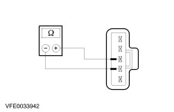
- Measure the resistance at the front wiper motor, between pin 2 and pin 3.
- CHECK the front wiper motor outside the park position:
- Measure the resistance at the front wiper motor, between pin 3 and pin 4.
- Is a resistance of less than 2 ohms registered?
2. If not, RENEW the front wiper motor. Component testing, RHD: Front wiper motor - CHECK the front wiper motor in the park position:
- Measure the resistance at the front wiper motor, between pin 3 and pin 4.
- CHECK the front wiper motor outside the park position:
- Measure the resistance at the front wiper motor, between pin 2 and pin 3.
- Is a resistance of less than 2 ohms registered?
2. If not, RENEW the front wiper motor. Wash/wipe switch Pin assignment: | Circuit to test | Connect a digital multimeter with the following connections | Set the switch to the following position | Switch is OK when the following test readings are seen | | Variable wipe times | 1 and 10 | 1 | 0.5 - 4 kOhm | | | | 2 | 4 -14 kOhm | | | | 3 | 14 -24 kOhm | | | | 4 | 24 -34 kOhm | | | | 5 | 34 -43 kOhm | | | | 6 | 43 -57 kOhm | | Flick wipe, front wiper | 6 and 9 | Flick wipe | Circuit closed | | | | Off | Circuit open | | | | Intermittent | Circuit open | | | | Slow | Circuit closed | | | | Fast | Circuit open | | Intermittent, front wiper | 6 and 10 | Flick wipe | Circuit open | | | | Off | Circuit open | | | | Intermittent | Circuit closed | | | | Slow | Circuit open | | | | Fast | Circuit open | | | 7 and 9 | Flick wipe | Circuit open | | | | Off | Circuit closed | | | | Intermittent | Circuit closed | | | | Slow | Circuit open | | | | Fast | Circuit open | | Slow wipe, front wiper | 6 and 9 | Flick wipe | Circuit closed | | | | Off | Circuit open | | | | Intermittent | Circuit open | | | | Slow | Circuit closed | | | | Fast | Circuit open | | Fast wipe, front wiper | 6 and 8 | Flick wipe | Circuit open | | | | Off | Circuit open | | | | Intermittent | Circuit open | | | | Slow | Circuit open | | | | Fast | Circuit closed | | Front washer system | 6 and 2 | Off | Circuit closed | | | | Front washer system on | Circuit open | | | 2 and 3 | Off | Circuit open | | | | Front washer system on | Circuit closed | | Rear window washer | 6 and 5 | Off | Circuit open | | | | Rear wiper on | Circuit closed | | | | Rear washer system on | Circuit closed | | | 3 and 4 | Off | Circuit open | | | | Rear wiper on | Circuit open | | | | Rear washer system on | Circuit closed | | Rear wiper | 5 and 3 | Off | Circuit closed | | | | Rear wiper on | Circuit open | | | | Rear washer system on | Circuit open | | | 4 and 6 | Off | Circuit closed | | | | Rear wiper on | Circuit closed | | | | Rear washer system on | Circuit open | | | 5 und 6 | Off | Circuit open | | | | Rear wiper on | Circuit closed | | | | Rear washer system on | Circuit closed | |