Flex AWD V6-3.5L (2009)

Compass: Initial Inspection and Diagnostic Overview
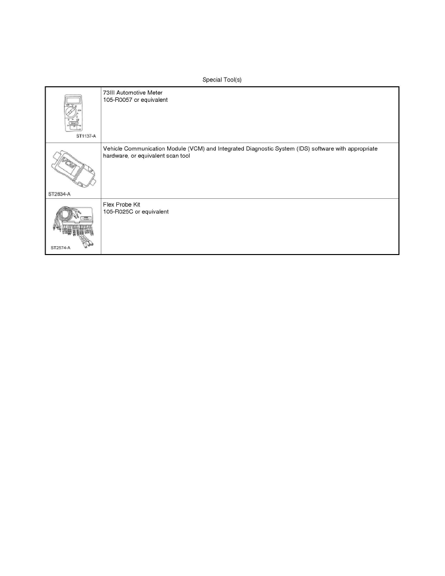
Special Tools Used With Diagnostics
Electronic Compass
Principles Of Operation
Electronic Compass
Principles of Operation
NOTE: The Smart Junction Box (SJB) is also known as the Generic Electronic Module (GEM).
NOTE: This procedure is only applicable to vehicles without navigation. For vehicles equipped with navigation, refer to Radio, Stereo, and Compact
Disc.
The compass display (located in the Front Display Interface Module (FDIM)) receives battery voltage from the SJB fuse 14 (10A). The compass module
(located integral to the auto-dimming interior mirror) provides vehicle directional inputs to the Instrument Cluster (IC), which sends the compass
information to the FDIM over the Medium Speed Controller Area Network (MS-CAN).
The compass is capable of self-calibrating. This decreases the need to manually set the compass. If the compass is displaying a heading (and not
displaying the CAL indicator), the compass is in auto-calibration mode. In this mode, the compass automatically calibrates for changes in vehicle
magnetics over the life of the vehicle. This auto-calibration mode makes sure that the compass heading is always accurate.
If the compass displays the CAL indicator for an extended period of time (longer than 5 seconds), this indicates the compass has been placed in the
manual calibration mode and therefore, requires manual calibration. The compass may temporarily display the CAL indicator if the vehicle
characteristics have changed (car wash, collision or other factors), with the CAL indicator turning off after the vehicle characteristics have returned to
normal.
Compass calibration/zone adjustment is controlled by the 7 and 9 buttons on the Front Controls Interface Module (FCIM), which provides access to the
calibration and zone adjustment procedures.
Inspection And Verification
Electronic Compass
Inspection and Verification
1. Verify the customer concern.
