
Flex AWD V6-3.5L (2009)
PINPOINT TEST C: THE IC DOES NOT RESPOND TO THE SCAN TOOL
NOTICE: Use the correct probe adapter(s) when making measurements. Failure to use the correct probe adapter(s) may damage the
connector.
NOTE: Failure to disconnect the battery when instructed will result in false resistance readings. Refer to Battery.
-------------------------------------------------
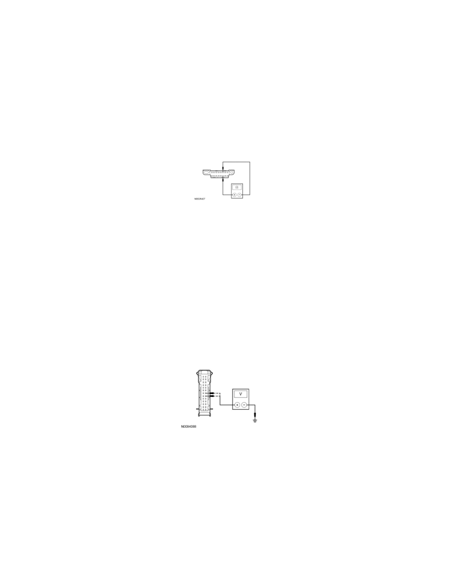
C1 CHECK THE HS-CAN TERMINATION RESISTANCE
-
Ignition OFF.
-
Disconnect: Negative Battery Cable.
-
Disconnect the scan tool cable from the Data Link Connector (DLC).
-
Measure the resistance between the DLC C251-6, circuit VDB04 (WH/BU), harness side and the DLC C251-14, circuit VDB05 (WH), harness
side.
-
Is the resistance between 54 and 66 ohms?
Yes
GO to C2.
No
GO to C4.
-------------------------------------------------
C2 CHECK THE IC VOLTAGE SUPPLY CIRCUITS FOR AN OPEN
-
Disconnect: IC C220.
-
Connect: Negative Battery Cable.
-
Ignition ON.
-
Measure the voltage between the IC C220-19, circuit SBP26 (YE/RD), harness side and ground; and between the IC C220-20, circuit CBP29
(WH/VT) harness side and ground.
-
Are the voltages greater than 10 volts?
Yes
GO to C3.
No
VERIFY the Smart Junction Box (SJB) fuse 26 (10A) or fuse 29 (5A) is OK. If OK, REPAIR the circuit in question. If not OK, REFER to the Wiring
Diagrams to identify the possible causes of the circuit short. CLEAR the DTCs. REPEAT the network test with the scan tool.
-------------------------------------------------
C3 CHECK THE IC GROUND CIRCUITS FOR AN OPEN
-
Ignition OFF.