
Flex AWD V6-3.5L (2009)
-
Ignition OFF.
-
Disconnect: Negative Battery Cable.
-
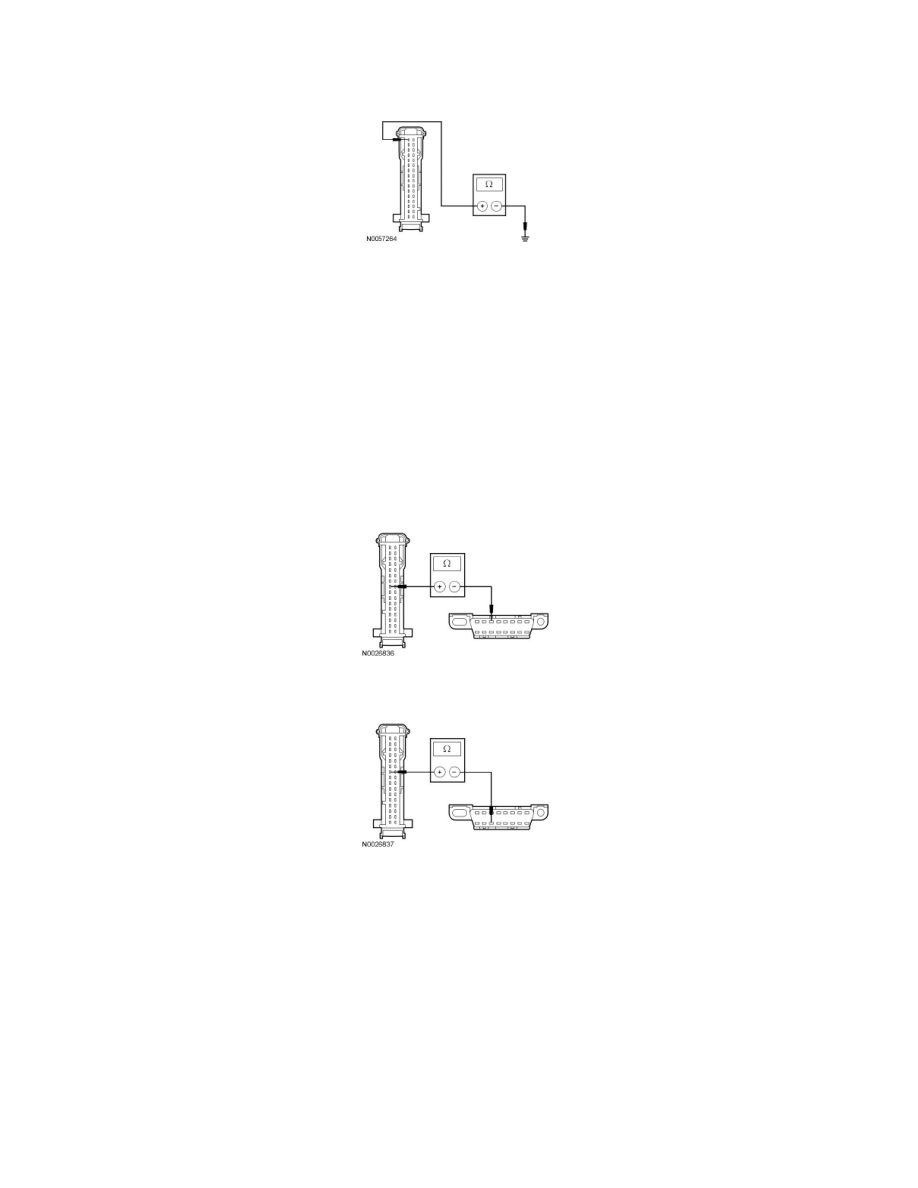
Measure the resistance between the RETM C9029-1, circuit GD114 (BK/BU), harness side and ground.
-
Is the resistance less than 5 ohms?
Yes
CONNECT the negative battery cable. GO to G3.
No
REPAIR the circuit. CONNECT the negative battery cable. CLEAR the DTCs. REPEAT the network test with the scan tool.
-------------------------------------------------
G3 CHECK THE MS-CAN CIRCUITS BETWEEN THE RETM AND THE DLC FOR AN OPEN
-
Measure the resistance between the RETM C9029-8, circuit VDB06 (GY/OG), harness side and the DLC C251-3, circuit VDB06 (GY/OG),
harness side.
-
Measure the resistance between the RETM C9029-7, circuit VDB07 (VT/OG), harness side and the DLC C251-11, circuit VDB07 (VT/OG),
harness side.
-
Are the resistances less than 5 ohms?
Yes
CONNECT the negative battery cable. GO to G4.
No
REPAIR the circuit. CONNECT the negative battery cable. CLEAR the DTCs. REPEAT the network test with the scan tool.
-------------------------------------------------
G4 CHECK FOR CORRECT RETM OPERATION
-
Disconnect the RETM connector.
-
Check for:
-
corrosion
-
damaged pins