
Flex AWD V6-3.5L (2009)
-
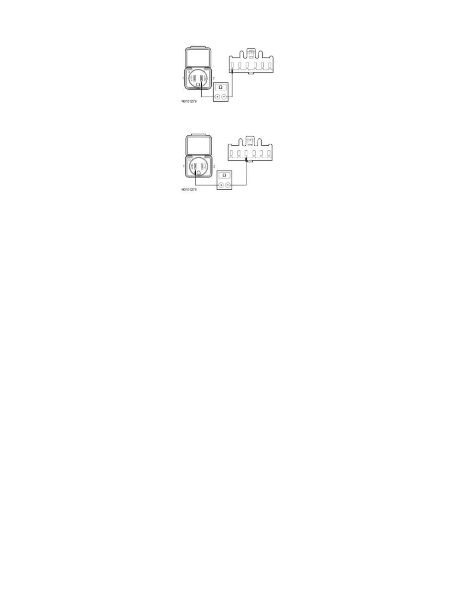
Measure the resistance between AC power point C301-1, component side and AC power point C301-2.
-
Measure the resistance between AC power point C301-3, component side and AC power point C301-1.
-
Are the resistances less than 5 ohms?
Yes
INSTALL a new DC/AC inverter. REFER to Direct Current/Alternating Current (DC/AC) Inverter See: Service and Repair/High Voltage
Converter/Inverter/Direct Current/Alternating Current (DC/AC) Inverter. TEST the system for normal operation.
No
INSTALL a new AC power point. REFER to Alternating Current (AC) Powerpoint See: Service and Repair/High Voltage
Converter/Inverter/Alternating Current (AC) Powerpoint. TEST the system for normal operation.
-------------------------------------------------
Pinpoint Test B: The DC/AC Inverter Does Not Operate Correctly - The AC Power Point LED
Indicator Is Never On
High-Voltage Converter/Inverter
Pinpoint Tests
Pinpoint Test B: The DC/AC Inverter Does Not Operate Correctly - The AC Power Point LED Indicator is Never On
Refer to Wiring Diagram Set 12, Charging System for schematic and connector information. See: Diagrams/Electrical Diagrams/Diagrams By Number
Normal Operation
The DC/AC inverter receives 12 volts DC on circuits SBP04 (GN/RD) and CBP35 (YE/GY) and is grounded on circuit GD148 (BK/GY). The incoming
DC power is internally converted to 60 cycle 110 volts AC power that is output to the AC power point on circuits HYA01 (OG/GN) (power) and
HYA02 (OG/WH) (neutral). If a fault in the system is detected, the LED flashes when the key is in the ON position. The LED continuously illuminates if
the system is operating correctly when the key is in the ON position.
This pinpoint test is intended to diagnose the following:
-
Fuses
-
Circuits
-
DC/AC inverter
-
AC power point
PINPOINT TEST B: THE DC/AC INVERTER DOES NOT OPERATE CORRECTLY - THE AC POWER POINT LED INDICATOR IS
NEVER ON
NOTICE: Use the correct probe adapter(s) when making measurements. Failure to use the correct probe adapter(s) may damage the
connector.