
Flex FWD V6-3.5L (2010)
-
Is the voltage greater than 10 volts?
Yes
INSTALL a new trailer tow connector. TEST the system for normal operation.
No
GO to AE5.
-------------------------------------------------
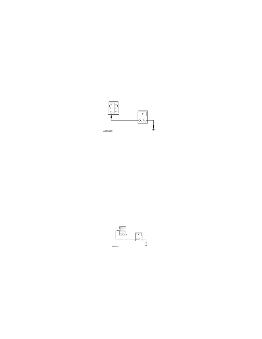
AE5 CHECK THE TBC MODULE VOLTAGE SUPPLY CIRCUIT FOR AN OPEN
-
Disconnect: TBC Module C2142.
-
Measure the voltage between the TBC module C2142-1, circuit CAT18 (YE/OG), harness side and ground.
-
Is the voltage greater than 10 volts?
Yes
GO to AE6.
No
VERIFY the BJB fuse 3 (30A) is OK. If OK, REPAIR circuit CAT18 (YE/OG) for an open. TEST the system for normal operation. If not OK, REFER
to the Wiring Diagrams to identify the possible causes of the circuit short. See: Diagrams/Electrical Diagrams/Diagrams By Number
-------------------------------------------------
AE6 CHECK THE STOPLAMP SWITCH INPUT CIRCUIT FOR AN OPEN
-
While applying the brake pedal, measure the voltage between the TBC module C2142-2, circuit CCB08 (VT/WH), harness side and ground.
-
Is the voltage greater than 10 volts?
Yes
GO to AE7.
No
REPAIR circuit CCB08 (VT/WH) for an open. TEST the system for normal operation.
-------------------------------------------------
AE7 CHECK FOR VOLTAGE TO THE TBC MODULE USING THE CONNECTOR GROUND