
Focus L4-2.0L (2009)
-------------------------------------------------
H5 CHECK FOR CORRECT SJB OPERATION
-
Disconnect all the SJB connectors.
-
Check for:
-
corrosion
-
damaged pins
-
pushed-out pins
-
Connect all the SJB connectors and make sure they seat correctly.
-
Operate the system and verify the concern is still present.
-
Is the concern still present?
Yes
INSTALL a new SJB. TEST the system for normal operation.
No
The system is operating correctly at this time. The concern may have been caused by a loose or corroded connector. CLEAR the DTCs. REPEAT the
self-test.
-------------------------------------------------
Pinpoint Test I: One or More Stoplamps Are Inoperative
Stoplamps
Pinpoint Tests
Pinpoint Test I: One Or More Stoplamps Are Inoperative
Refer to Wiring Diagram Set 90, Turn Signal/Stop/Hazard Lamps for schematic and connector information. See: Diagrams/Electrical
Diagrams/Diagrams By Number
Normal Operation
When the brake pedal is applied, the stoplamp switch routes voltage to the Smart Junction Box (SJB) and the high mounted stoplamp through circuit
CCB08 (VT/WH). When the SJB detects the brake pedal is applied, the SJB provides voltage to the LH and RH rear stoplamps through circuits CLS18
(GY/BN) and CLS19 (VT/OG). Ground for the all the stoplamps is provided through circuit GD110 (BK/WH).
The SJB fuse 6 (20A) supplies voltage for all the stop and turn lamps.
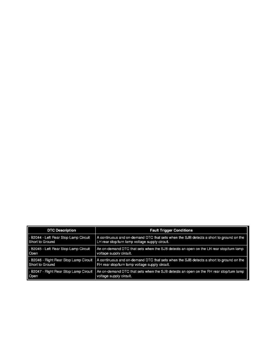
B2044-B2047
This pinpoint test is intended to diagnose the following:
-
Fuse
-
Wiring, terminals or connectors
-
Bulb holder
-
High mounted stoplamp
-
SJB
PINPOINT TEST I: ONE OR MORE STOPLAMPS ARE INOPERATIVE