
Focus L4-2.0L (2009)
No
REPAIR the DLC as necessary. CLEAR the DTCs. REPEAT the network test with the scan tool.
-------------------------------------------------
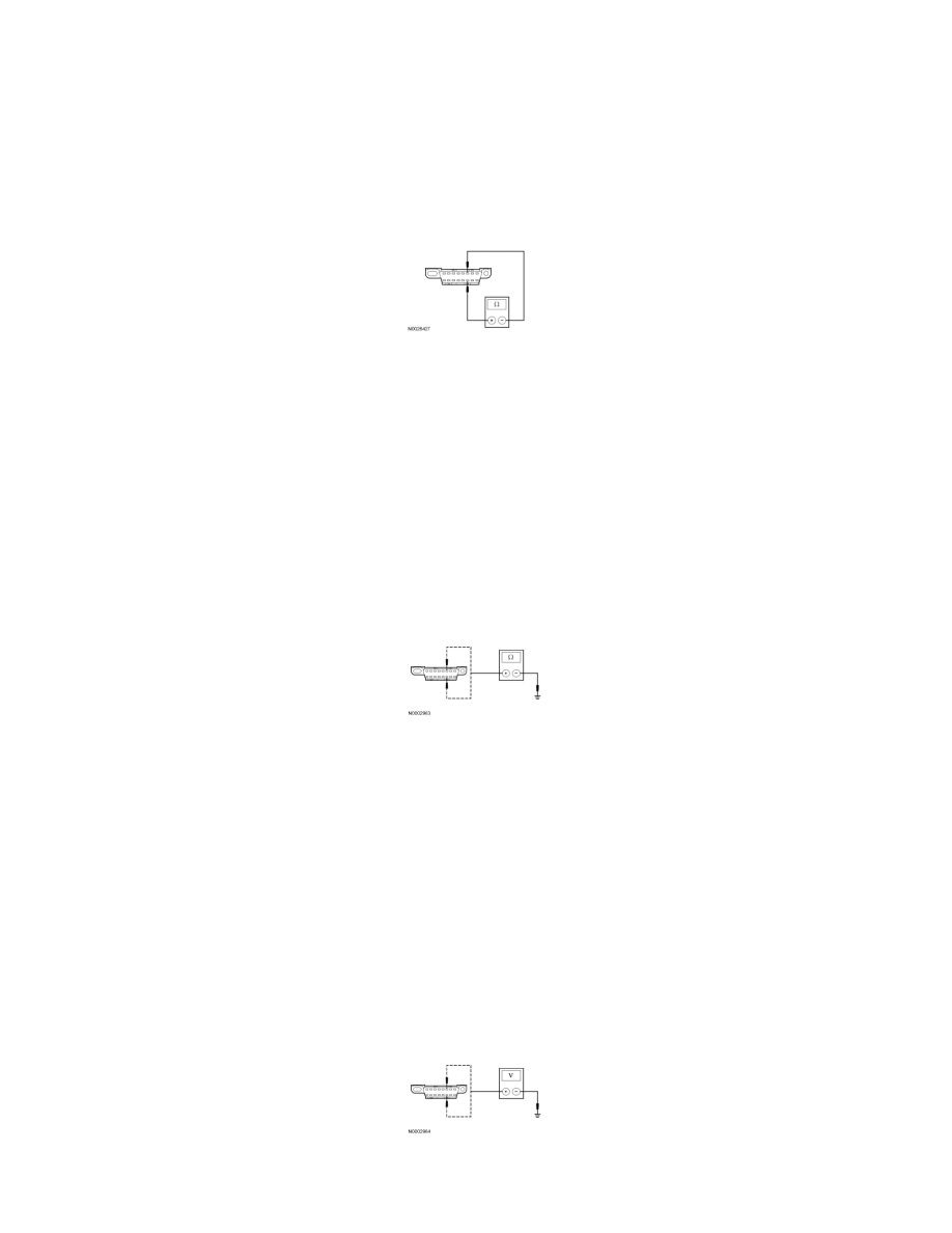
N2 CHECK THE HS-CAN TERMINATION RESISTANCE
-
Disconnect: Negative Battery Cable.
-
Measure the resistance between the DLC C251-6, circuit VDB04 (WH/BU), harness side and the DLC C251-14, circuit VDB05 (WH), harness
side.
-
Is the resistance between 54 and 66 ohms?
Yes
GO to N3.
No
Go To Pinpoint Test O. See: Pinpoint Test O: No High Speed Controller Area Network (HS-CAN) Communication, All Modules Are Not Responding
-------------------------------------------------
N3 CHECK THE HS-CAN (+) AND HS-CAN (-) CIRCUITS FOR A SHORT TO GROUND
-
Measure the resistance between the DLC C251-6, circuit VDB04 (WH/BU), harness side and ground; and between the DLC C251-14, circuit
VDB05 (WH), harness side and ground.
-
Are the resistances greater than 1,000 ohms?
Yes
GO to N4.
No
Go To Pinpoint Test O. See: Pinpoint Test O: No High Speed Controller Area Network (HS-CAN) Communication, All Modules Are Not Responding
-------------------------------------------------
N4 CHECK THE HS-CAN (+) AND HS-CAN (-) CIRCUITS FOR A SHORT TO VOLTAGE
-
Connect: Negative Battery Cable.
-
Ignition ON.
-
Measure the voltage between the DLC C251-6, circuit VDB04 (WH/BU), harness side and ground; and between the DLC C251-14, circuit
VDB05 (WH), harness side and ground.
-
Are the voltages greater than 6 volts?