
Focus L4-2.0L DOHC VIN 5 (2003)
^
Stop lamp switch (colored grey) XX mm = 21 mm.
^
Starter safety switch (colored black) XX mm = 26 mm.
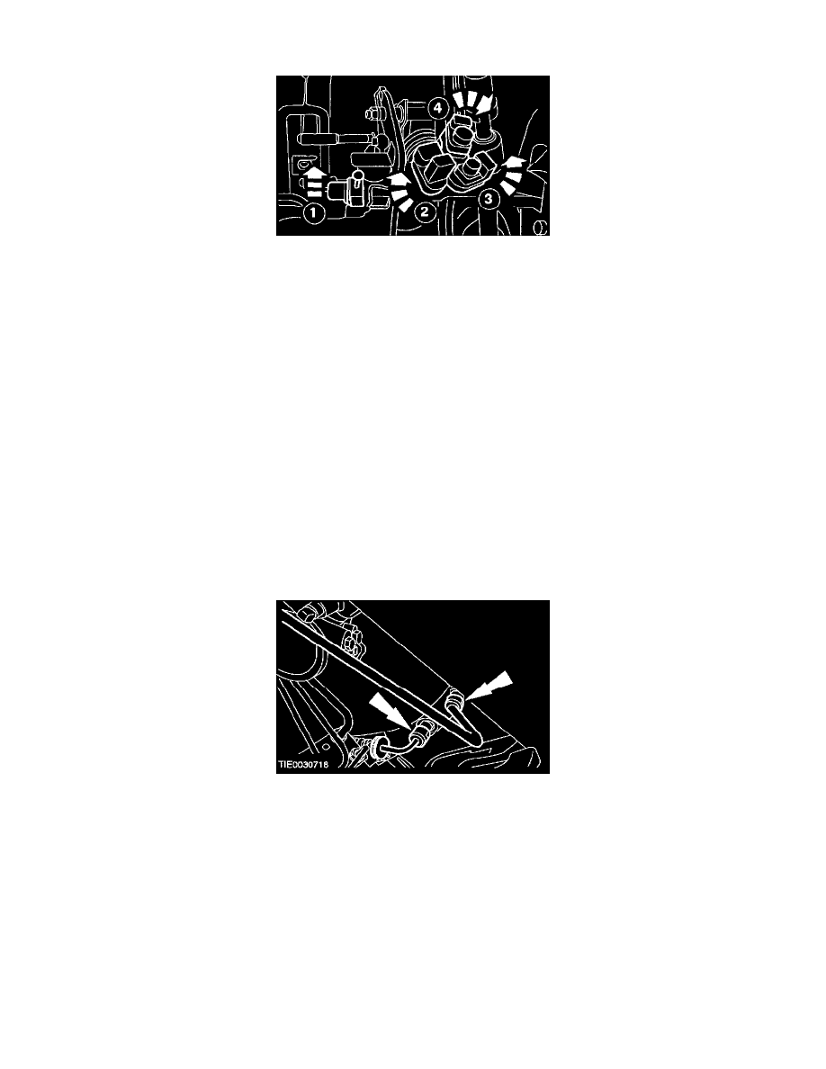
7. CAUTION: When installing the switches, the stop lamp switch is rotated to the counterclockwise-and the remaining switches are rotated to the
clockwise. Failure to follow this instruction will result in the switch plungers binding inside the switch.
CAUTION: Make sure the switches are correctly installed.
NOTE: The speed control deactivation switch and the stop lamp switch are automatically adjusted during installation.
NOTE: A slight ratcheting noise and feel during installation of the speed control deactivation switch and the stop lamp switch is normal.
Install the switches to the pedal assembly.
1
Speed control deactivation switch (colored green).
2
Stop lamp switch (colored grey).
3
Clutch position switch (colored red).
4
Starter safety switch (colored black).
8. NOTE: The colors of the electrical connectors and the switches are identical.
Connect the electrical connectors to the pedal assembly switches.
9. NOTE: A slight ratcheting noise and feel during switch adjustment is normal.
Adjust the starter safety switch (colored black) by pressing and then releasing the clutch pedal.
10. NOTE: Install new O-ring seals if necessary.
Connect the clutch master cylinder and slave cylinder fluid supply lines to the clutch master cylinder.
^
Insert the clips.