
Focus L4-2.0L VIN N (2006)
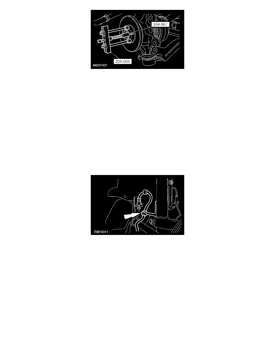
3. CAUTION: Make sure the ball joint heat shield is installed on the lower arm to prevent damage to the ball joint.
Remove the special tool, position the heat shield on the wheel knuckle, insert the ball joint stud into the wheel knuckle and install the bolt and nut.
^
Tighten to 63 Nm (46 ft. lbs.).
4. WARNING: Install a new tie-rod end nut. Failure to follow this instruction may result in personal injury.
Attach the tie-rod end to the wheel knuckle and install the nut.
^
Tighten to 35 Nm (26 ft. lbs.).
Vehicles with anti-lock brakes
5. Position the wheel speed sensor and install the bolt.
^
Tighten to 9 Nm (80 inch lbs.).
All vehicles
6. Position the brake disc.
7. Position the caliper and anchor plate assembly and install the bolts.
^
Tighten to 133 Nm (98 ft. lbs.).
8. Attach the brake hose to the support bracket.
9. Tighten the strut upper nuts to 30 Nm (22 ft. lbs.).
10. CAUTION: Install and tighten the new wheel hub nut and washer to specification in a continuous rotation. Always install a new wheel hub nut
and washer after loosening or when not tightened to specification in a continuous rotation.
CAUTION: Always tighten a new wheel hub nut and washer with a torque wrench. Never use power tools to tighten the wheel hub nut
and washer. Power tools may damage the nut or the halfshaft.
CAUTION: Do not tighten the front wheel hub nut with the vehicle on the ground. The nut must be tightened to specification before the
vehicle is lowered onto the wheels. Wheel bearing damage will occur if the wheel bearing is loaded with the weight of the vehicle applied.
NOTE: Apply the brake to keep the halfshaft from rotating.
Install the new front wheel hub nut.
^
Tighten to 270 Nm (199 ft. lbs.).
11. If removed, install the wheel cover.