
Focus L4-2.3L VIN Z (2003)
Information Bus: Testing and Inspection
Module Communications Network
Initial Inspection
INSPECTION AND VERIFICATION
1. Verify the customer concern.
2. Visually inspect obvious signs of mechanical or electrical damage.
VISUAL INSPECTION CHART
Electrical
-
Fuse(s)
-
Wiring harness
-
Loose or corroded connector(s)
-
Damaged connector(s)
3. If an obvious cause for an observed or reported concern is found, correct the cause (if possible) before proceeding to the next step.
4. If the cause is not visually evident, connect the diagnostic tool to the data link connector and select the vehicle to be tested from the diagnostic tool
menu. If the diagnostic tool does not communicate with the vehicle:
-
check that the program card is correctly installed.
-
check the connections to the vehicle.
-
check the ignition switch position.
If the diagnostic tool still does not communicate with the vehicle, GO to Pinpoint Test J. See: Pinpoint Tests/Pinpoint Tests/Test J
5. GO to Pinpoint Test PC. See: Pinpoint Tests/Pinpoint Test PC (Precheck)
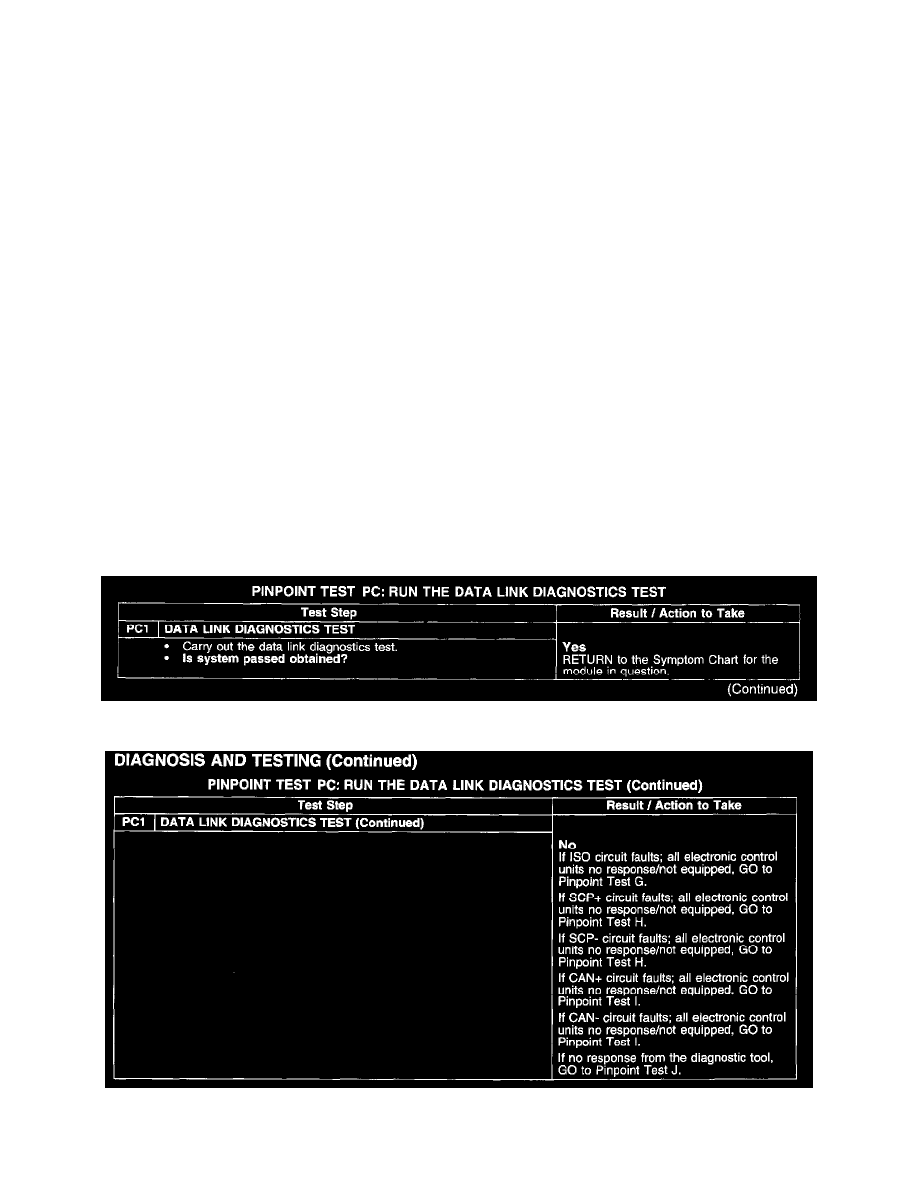
Pinpoint Test PC (Precheck)
PINPOINT TEST PC: RUN THE DATA LINK DIAGNOSTICS TEST
Test PC1
Test PC1 Continued