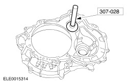
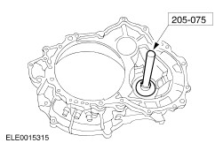
| Assembly Special Tool(s) | | Preload Gauge 205-067 (15-041) | | | Installer, Differential Bearing Cone 205-073 (15-034) | | | Installer, Rear Wheel Hub Seal 205-075 (15-036) | | | Installer, Timing Cover Seal 303-255 (21-136) | | | Compressor, Valve Spring 303-364 (21-158) | | | Installer, Extension Housing Seal 307-028 (17-002) | | | Depth Gauge, Shim Selection 307-300-02 (17-055-02) | | | Holding Tool, Final Drive Input Gear 307-413 (17-079) | | | Socket, Final Drive Input Nut 307-414 (17-080) | | | Alignment Gauge, TR Sensor 307-415 (17-081) | | | Adjustment Bolt, Transmission Band 307-416 (17-082) | | | Gauge, Differential/Transfer Gear Bearing Shim 307-417 (17-083) | | | Holding Fixture, Final Drive 307-420 (17-085) | | | Gauge, Transmission End Play 307-430 (17-084) | | | Remover, Input Shaft Fifth Gear 308-082 (16-035) | | | Installer, Differential Double Lip Seal 308-203 (16-066) | Materials Name Specification Thread sealer TN-YS5J-M4G9107-AA Loctite 5699 WSS-M4G-320-A3 Assembly | | -
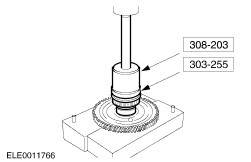
Using an arbor press and the special tools, seat the final drive input gear bearing. | | | -
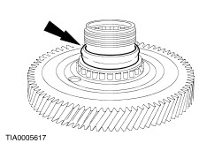
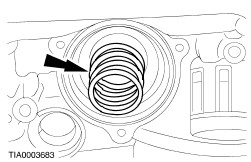
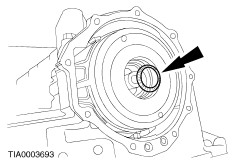
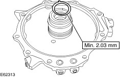
Install a new collapsible spacer. | | | -
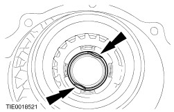
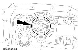
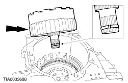
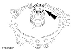
Using the special tool, position the final drive input gear. | | | -
CAUTION:Hold the final drive input gear while installing the final drive input gear bearing to prevent it from falling out of the transaxle case. Rotate the transaxle 180 degrees. | | | -
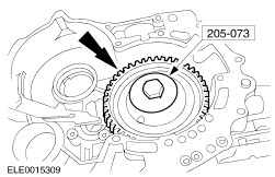
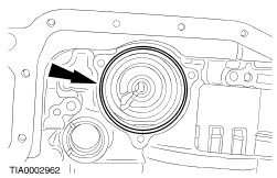
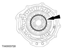
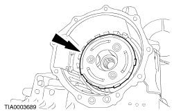
Using the special tools, install the final drive input gear bearing. | | | -
Rotate the transaxle 180 degrees. | | | -
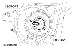
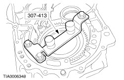
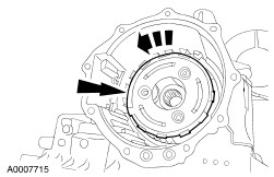
Using the special tool, lock the final drive input gear. | | | -
Rotate the transaxle 180 degrees. | | | -
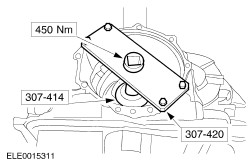
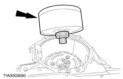
NOTE:A high tightening torque specification (between 400-450 Nm) is necessary to crush the collapsible spacer for correct bearing preload. NOTE:If the preload is too high a new collapsible spacer must be installed. Using the special tools, tighten the nut to achieve the preload specification. | | | -
Rotate the transaxle 180 degrees. | | | -
NOTE:Make sure that the final drive rotates. Unlock the special tool. | | | -
Rotate the transaxle 180 degrees. | | | -
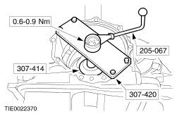
CAUTION:Make sure that the bearing preload is within specification. NOTE:Rotate the gear ten times to make sure that the bearings are correctly seated. Using the special tools, measure the rotating torque. | | | -
After achieving the correct torque, remove the special tools and stake the nut to prevent movement. | | | -
Rotate the transaxle 180 degrees. | | | -
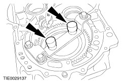
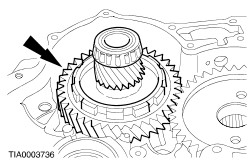
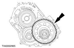
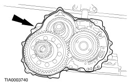
Position the transfer shaft gears in the transaxle case. | | | -
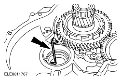
Install the parking pawl return spring. | | | -
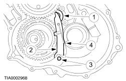
Connect the parking pawl return spring. - Install the parking pawl abutment.
- Install the lever.
- Install the pin.
- Reconnect the pawl spring.
| | | -
Install the parking pawl cover. | | | -
Install the differential case assembly. | | | -
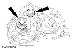
Install the bearing cups. | | | -
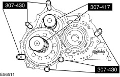
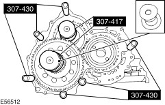
Install the special tools. | | | -
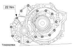
NOTE:The converter housing cover must be installed evenly or an incorrect reading will result. Assemble the transaxle for end play measurement. - Install the converter housing.
- Install the long bolts and seat the converter housing.
- Install the short bolts.
| | | -
Remove the converter housing. - Remove the bolts.
- Remove the converter housing.
| | | -
NOTE:Do not move the special tool plunger, settings are made. Remove the special tools. | | | -
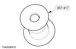
NOTE:If the plunger is above the contact surface, the reading will be incorrect. To determine the correct transfer shaft shim, measure the depth of the plunger on the special tool and select the correct transfer shaft shim.
For additional information, refer to: Specifications (307-01 Automatic Transmission/Transaxle - Vehicles With: 4F27E, Specifications).
| | | -
NOTE:If the plunger is above the contact surface, the reading will be incorrect. To determine the correct differential shaft shim, measure the depth of the plunger on the special tool and select the correct differential shaft shim.
For additional information, refer to: Specifications (307-01 Automatic Transmission/Transaxle - Vehicles With: 4F27E, Specifications).
| | | -
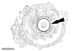
Using the special tool, install the correct transfer shaft shim and differential case bearing cup into the converter housing. | | | -
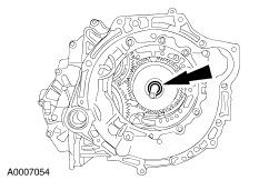
Using the special tool, install the correct differential shaft shim and differential case bearing cup in to the converter housing. | | | -
NOTE:The components must be assembled within 15 minutes. | | | -
Install the converter housing. | | | -
Install the servo piston return spring. | | | -
Install the servo piston. | | | -
NOTE:The three bolts need to be loosely installed, then tightened in sequence to compress the servo piston return spring evenly. Install the servo piston cover. | | | -
Install the shifter assembly and bolt. | | | -
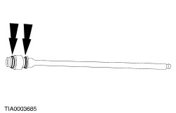
NOTE:Lubricate the O-ring prior to assembly. Install the new O-rings on the manual lever shaft. | | | -
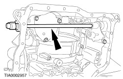
Install the manual lever shaft. | | | -
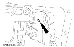
NOTE:The roll pin does not need to sit flush with the shifter assembly. Install the manual lever shaft roll pin. | | | -
Loosely install the transmission range (TR) sensor. | | | -
NOTE:The neutral drive accumulator springs are thinner than the 1-2 accumulator springs. Install the neutral drive accumulator springs. | | | -
Install the neutral drive accumulator piston. | | | -
Install the 1-2 accumulator springs. | | | -
Install the 1-2 accumulator piston. | | | -
Lubricate and install the transaxle internal harness electrical connector. | | | -
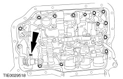
NOTE:Make sure that the manual valve is in the manual control valve shift lever. NOTE:Do not fully tighten the bolts at this stage. Install the main control valve body. | | | -
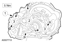
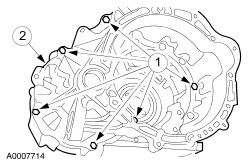
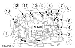
Tighten the main control valve body bolts. - Tighten the bolts in the sequence shown.
| | | -
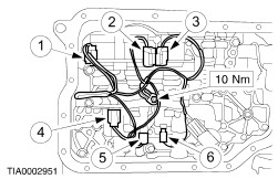
NOTE:It is necessary to connect the connectors in the same positions as noted in disassembly. Connector color letters are cast into the solenoid body. Install the main control wire harness, connect the electrical connectors and install the ground wire bolt. - Solenoid SSC; Color W (/Neutral/White)
- Solenoid SSE; Color G (Green)
- Solenoid SSD; Color L (Blue)
- Solenoid EPC; Color B (Black)
- Solenoid SSA; Color N (Neutral)
- Solenoid SSB; Color B (Black)
| | | -
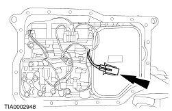
Install the fluid filter. | | | -
Connect the transmission fluid temperature (TFT) sensor. | | | -
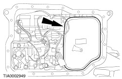
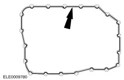
Apply a one and a half millimeter thick bead of Loctite 5699 to the transaxle fluid pan. | | | -
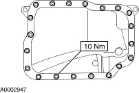
Install the transaxle fluid pan. | | | -
Rotate the transaxle 180 degrees. | | | -
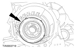
Install the low and reverse clutch piston. | | | -
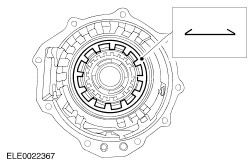
NOTE:Make sure that the clutch return spring is inserted with the tabs facing upwards Install the low and reverse clutch return spring. | | | -
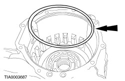
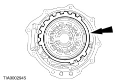
Install the bevel ring with the outer edge uppermost. | | | -
Inspect the position of the bevel ring. - Make sure the low and reverse clutch piston is seated.
- Make sure the bevel ring is installed with the inside edge facing down.
| | | -
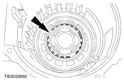
Install the low one-way clutch inner race. | | | -
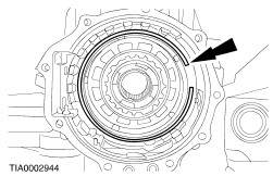
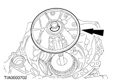
NOTE:The opening of the retaining ring must be at the ten o'clock position. Install the low one-way clutch retaining ring. | | | -
Install the low and reverse gear plate and pressure plate. | | | -
Install the low reverse gear clutch plate selective retaining ring. - Check the clutch clearance.
For additional information, refer to: Specifications (307-01 Automatic Transmission/Transaxle - Vehicles With: 4F27E, Specifications).
| | | -
NOTE:Make sure that the snap ring is installed before installing the planet assembly. Install the planet assembly. | | | -
CAUTION:The edge of the planet assembly must fit flush with the transaxle case. Inspect the planet assembly installation. | | | -
CAUTION:The planet assembly must only rotate counterclockwise. Check that the one way clutch is installed correctly. - Rotate the planet assembly clockwise and counterclockwise.
| | | -
Install the intermediate and overdrive drum assembly. | | | -
Install the intermediate and overdrive brake band. | | | -
Install the direct clutch cylinder thrust bearing with the rollers facing up. | | | -
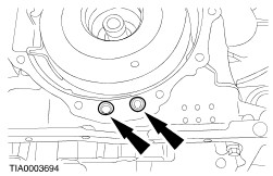
Install new end cover to case seals. | | | -
Install new end cover seals. | | | -
Install the direct clutch hub bearing shim and an additional shim to increase the total shim thickness to the specification shown or greater. | | | -
NOTE:Make sure the cover is seated down on both shims. NOTE:Take measurements from several positions and calculate the average gap. Measure the gap between the transaxle end cover and the transaxle assembly. - Install the transaxle end cover on the transaxle assembly.
- Measure the gap between the transaxle end cover and the transaxle assembly.
| | | -
Remove the transaxle end cover. | | | -
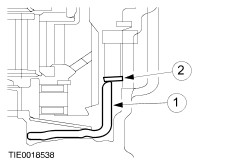
NOTE:The clearance for the direct clutch shim is 0.25 - 0.50 mm. NOTE:The correct shim thickness is between the minimum and maximum value. Select and install the correct direct clutch hub bearing shim. - Line 1: total amount of shim thickness used during transaxle end cover mock up.
- Line 2: measure the gap between transaxle end cover and transaxle case.
- Line 3: subtract Line 2 from Line 1 to obtain the actual clearance.
- Line 4: subtract 0.25 mm from Line 3 for maximium shim thickness.
- Subtract 0.50 mm from Line 3 for the minimum shim thickness.
| | | -
CAUTION:Make sure that the sealant does not enter the fluid return holes. Apply a one millimeter thick bead of Loctite 5699 to the transaxle end cover. | | | -
Install the transaxle end cover. | | | -
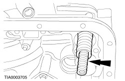
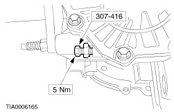
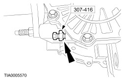
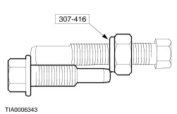
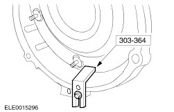
Using the special tool, collapse the band to specification then slacken three and a half turns. | | | -
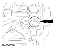
Holding the special tool, lightly seat the nut against the transaxle case, then remove the special tool without changing the relationship of the nut on the bolt. | | | -
Using the special tool, select a band bolt that measures from the end of the bolt to the face of the nut as shown. | | | -
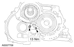
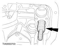
NOTE:Apply thread sealer to the bolt. Install the band anchor bolt. | | | -
Rotate the transaxle 180 degrees. | | | -
Install the forward clutch hub. | | | -
Install the forward clutch assembly. | | | -
Install the forward clutch thrust washer. | | | -
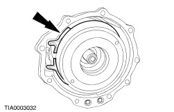
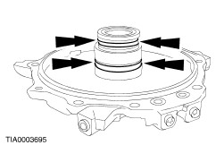
Lubricate and install new fluid pump seals. | | | -
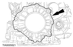
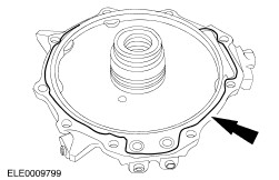
NOTE:Do not force the pump down at this time. Install the fluid pump. | | | -
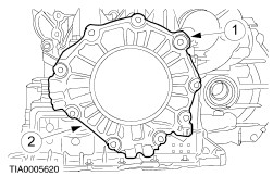
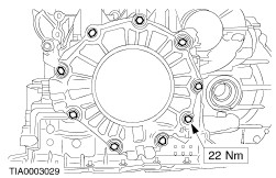
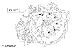
Install the fluid pump. - Use the bolts to seat the fluid pump.
- Tighten the retaining bolts in an alternating sequence.
| | | -
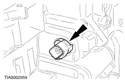
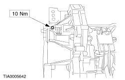
Install the output shaft speed (OSS) sensor. | | | -
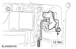
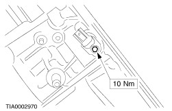
NOTE:Apply thread sealer to the bolt. Install the turbine shaft speed (TSS) sensor. | | | -
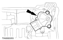
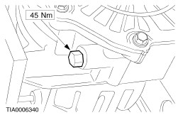
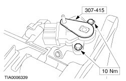
Using the special tool, align the TR sensor and tighten the retaining bolts. | | | -
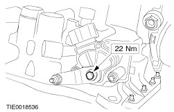
CAUTION:Do not use air tools on this bolt. Hold the manual control lever while tightening the manual control lever retaining bolt. Install the manual control lever. | | | -
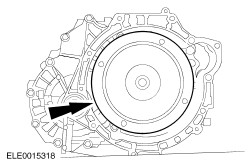
Install the torque converter. | | | -
Using the special tool, secure the torque converter. | | |