| Removal and Installation Worldwide diagnostic system (WDS) CAUTION:If brake fluid is spilt on the paintwork, the affected area must be immediately washed down with cold water. | | -
Obtain and record the stability assist program code using WDS. | | | -
CAUTION:The brake fluid reservoir cap must not become contaminated. Remove the brake fluid reservoir cap. | | | -
NOTE:It will be necessary to carry out this step on both sides in order to completely drain the brake fluid reservoir. Drain the brake fluid reservoir. - Connect one end of a suitable piece of clear plastic pipe to the bleed nipple and place the other end into a suitable container.
- Loosen the bleed nipple.
- Depress the brake pedal until all the brake fluid is drained from the brake fluid reservoir.
- Tighten the bleed nipple.
| | | -
Install the brake fluid reservoir cap. | | | -
Remove the battery tray.
For additional information, refer to: Battery Tray - 1.4L Duratec-16V (Sigma)/1.6L Duratec-16V (Sigma)/1.8L Duratec-HE (MI4)/2.0L Duratec-HE (MI4) (414-01 Battery, Mounting and Cables, Removal and Installation) /
Battery Tray - 1.6L Duratorq-TDCi (DV) Diesel/1.8L Duratorq-TDCi (Lynx) Diesel/2.0L Duratorq-TDCi (DW) Diesel (414-01 Battery, Mounting and Cables, Removal and Installation).
| | | -
CAUTION:Cap the stability assist module electrical connector and socket to prevent dirt and fluid ingress. Disconnect the stability assist module electrical connector. - Depress the locking tangs.
- Release the retainer.
| 7. Remove the components in the order indicated in the following illustration(s) and table(s). 4 - HCU and stability assist module assembly support bracket retaining bolt 6 - HCU and stability assist module assembly to support bracket retaining bolts 7 - Stability assist module to HCU retaining bolts 8. To install, reverse the removal procedure. | | -
Bleed the brake system.
For additional information, refer to: Brake System Bleeding (206-00 Brake System - General Information, General Procedures) /
Brake System Pressure Bleeding (206-00 Brake System - General Information, General Procedures).
| | | -
WARNING:The stability assist program must be re-configured. Failure to follow this instruction may result in personal injury. Configure the stability assist program using WDS. | Removal Details Item 1 : Hydraulic control unit (HCU) to brake master cylinder brake tubes | | -
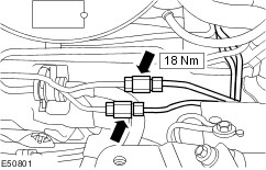
CAUTION:Cap the brake tubes to prevent fluid loss or dirt ingress. CAUTION:Plug the HCU ports to prevent fluid loss or dirt ingress. NOTE:Make a note of the position of the brake tubes, to aid installation. Disconnect the brake tubes from the HCU. - Detach the tubes from the securing clips.
| | | -
Remove the HCU to master cylinder brake tubes. | Item 2 : HCU to front brake tubes | | -
CAUTION:Cap the brake tubes to prevent fluid loss or dirt ingress. CAUTION:Plug the HCU ports to prevent fluid loss or dirt ingress. NOTE:Make a note of the position of the brake tubes, to aid installation. Disconnect the brake tubes from the HCU. | | | -
CAUTION:Cap the brake tubes to prevent fluid loss or dirt ingress. Remove the HCU to right-hand front caliper brake tube. | Item 3 : HCU to rear brake tubes | | -
CAUTION:Cap the brake tubes to prevent fluid loss or dirt ingress. CAUTION:Plug the HCU ports to prevent fluid loss or dirt ingress. NOTE:Make a note of the position of the brake tubes, to aid installation. Disconnect the brake tubes from the HCU. - Detach the tubes from the securing clips.
| | | -
CAUTION:Cap the brake tubes to prevent fluid loss or dirt ingress. Remove the HCU to rear brake tubes. | Item 8 : HCU WARNING:Do not touch the HCU or stability assist module contact points as this may affect the electronic program. Failure to follow this instruction may result in personal injury. CAUTION:Plug the stability assist module ports to prevent fluid loss or dirt ingress. Installation Details Item 8 : HCU WARNING:Do not install a damaged HCU. Failure to follow this instruction may result in personal injury. WARNING:Make sure that the HCU is correctly located on the stability assist module. Failure to follow this instruction may result in personal injury. CAUTION:Do not drop or knock the HCU. Failure to follow this instruction will cause damage to the hydraulic components. CAUTION:Do not remove the stability assist module port blanking plugs until the HCU is ready to be installed. Item 5 : HCU and stability assist module assembly WARNING:Do not install a damaged HCU and stability assist module assembly. Failure to follow this instruction may result in personal injury. CAUTION:Do not drop or knock the HCU and stability assist module assembly. Failure to follow this instruction will cause damage to the electronic and hydraulic components. Item 3 : HCU to rear brake tubes CAUTION:Do not remove the brake tube blanking caps or HCU port blanking plugs until the brake tubes are ready to be installed. Item 2 : HCU to front brake tubes CAUTION:Do not remove the brake tube blanking caps or HCU port blanking plugs until the brake tubes are ready to be installed. Item 1 : Hydraulic control unit (HCU) to brake master cylinder brake tubes CAUTION:Do not remove the brake tube blanking caps or HCU port blanking plugs until the brake tubes are ready to be installed. |