| Symptom | Possible Sources | Action |
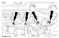
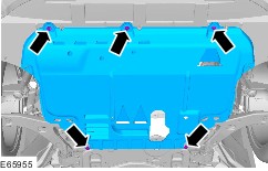
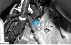
| Loss of oil | * Oil leaks on components that are either coated in oil themselves or on components local to them. | * CHECK for evidence of oil leaks on components. Use an ultraviolet (UV) leak tester if an oil leak is not evident. INSTALL new gaskets or components as required. |
| * Internal or external leak at the oil cooler. | * CHECK the coolant expansion tank for a film of oil on the coolant surface. INSTALL a new oil cooler or oil cooler gasket. |
| * Leak at the crankshaft seal. | * INSTALL a new crankshaft seal. |
| * Leaks from oil carrying components or basic engine. | * CHECK for cracks in oil-carrying components of the basic engine by means of a UV leak test. INSTALL new components or seals as necessary. |
| Oil consumption | * Use of the wrong type of engine oil. | * DETERMINE the last type of engine oil used and compare with the specification. Change the engine oil to the specification. |
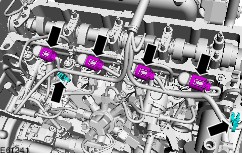
| * Faulty positive crankcase ventilation (PCV) system. - Hoses or ventilation or breather valves are blocked. This causes excessive pressure in the crankcase which causes more oil to enter the combustion chamber. - PCV oil separator is faulty and engine oil can enter the combustion chamber through the intake manifold. | * CHECK if the PCV system is operating correctly and repair as necessary. Engine - 1.4L Duratec-16V (Sigma)/1.6L Duratec-16V (Sigma) -
REFER to: Engine Emission Control (303-08A Engine Emission Control - 1.4L Duratec-16V (Sigma)/1.6L Duratec-16V (Sigma)/1.6L Duratec-16V Ti-VCT (Sigma), Diagnosis and Testing).
Engine - 1.8L Duratec-HE (MI4)/2.0L Duratec-HE (MI4) -
REFER to: Engine Emission Control (303-08B Engine Emission Control - 1.8L Duratec-HE (MI4)/2.0L Duratec-HE (MI4), Diagnosis and Testing).
Engine - 2.5L Duratec-ST (VI5) -
REFER to: Engine Emission Control (303-08G, Diagnosis and Testing).
Engine - 1.6L Duratorq-TDCi (DV) Diesel -
REFER to: Engine Emission Control (303-08C Engine Emission Control - 1.6L Duratorq-TDCi (DV) Diesel, Diagnosis and Testing).
Engine - 2.0L Duratorq-TDCi (DW) Diesel -
REFER to: Engine Emission Control (303-08D Engine Emission Control - 2.0L Duratorq-TDCi (DW) Diesel, Diagnosis and Testing).
Engine - 1.8L Duratorq-TDCi (Kent) Diesel -
REFER to: Engine Emission Control (303-08F Engine Emission Control - 1.8L Duratorq-TDCi (Kent) Diesel, Diagnosis and Testing).
|
| * Turbocharger seals. | * INSTALL a new turbocharger. Engine - 2.5L Duratec-ST (VI5) -
REFER to: Turbocharger (303-04E, Removal and Installation) /
Turbocharger - 1.6L Duratorq-TDCi (DV) Diesel (90 PS) (303-04I Fuel Charging and Controls - Turbocharger, Removal and Installation) /
Turbocharger - 1.6L Duratorq-TDCi (DV) Diesel (110 PS) (303-04I Fuel Charging and Controls - Turbocharger, Removal and Installation) /
Turbocharger - 1.6L Duratorq-TDCi (DV) Diesel (110 PS), VIN Plate Emission Level Code: K (303-04I Fuel Charging and Controls - Turbocharger, Removal and Installation) /
Turbocharger - 1.8L Duratorq-TDCi (Kent) Diesel (303-04I Fuel Charging and Controls - Turbocharger, Removal and Installation) /
Turbocharger - 2.0L Duratorq-TDCi (DW) Diesel (303-04I, Removal and Installation).
|
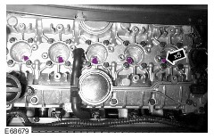
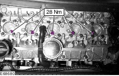
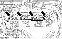
| * Damaged gaskets or mating surfaces. - Cylinder head gasket is damaged or mating face are warped. - Valve stem seals are worn and engine oil can enter the combustion chamber between the valve stem and the valve stem guide. | * CHECK the gaskets and mating surfaces for damage. - Remove the cylinder head. CHECK the mating faces, cylinder head gasket and the evenness of the cylinder head and engine block mating faces. - INSTALL new valve seals. Engine - 1.4L Duratec-16V (Sigma)/1.6L Duratec-16V (Sigma) -
REFER to: Valve Seals (303-01A Engine - 1.4L Duratec-16V (Sigma)/1.6L Duratec-16V (Sigma), In-vehicle Repair).
Engine - 1.6L Duratec-16V Ti-VCT
REFER to: Valve Seals (303-01B Engine - 1.6L Duratec-16V Ti-VCT (Sigma), In-vehicle Repair).
Engine - 1.8L Duratec-HE (MI4)/2.0L Duratec-HE (MI4) -
REFER to: Valve Seals (303-01C Engine - 1.8L Duratec-HE (MI4)/2.0L Duratec-HE (MI4), In-vehicle Repair).
Engine - 2.5L Duratec-ST (VI5) -
REFER to: Valve Stem Seals (303-01D, Removal and Installation).
Engine - 1.6L Duratorq-TDCi (DV) Diesel -
REFER to: Valve Seals (303-01E Engine - 1.6L Duratorq-TDCi (DV) Diesel, In-vehicle Repair).
Engine - 2.0L Duratorq-TDCi (DW) Diesel -
REFER to: Valve Seals (303-01F Engine - 1.8L Duratorq-TDCi (Kent) Diesel, In-vehicle Repair).
Engine - 1.8L Duratorq-TDCi (Kent) Diesel -
REFER to: Valve Seals (303-01G Engine - 2.0L Duratorq-TDCi (DW) Diesel, In-vehicle Repair).
|
| * Piston ring or cylinder liner wear. | * INSTALL new components as necessary. |
| * Damaged cylinder liners or excessive clearance of engine components. - Pistons. - Piston rings (clearance in groove and end gap). - Cylinder liners. | * CHECK the running surfaces and clearances of the individual engine components. INSTALL new components as necessary. INSTALL a new cylinder block if necessary. * Check the pistons and piston rings. REFER to: (303-00 Engine System - General Information) Piston Inspection (General Procedures), Piston Pin to Bore Diameter (General Procedures), Piston Diameter (General Procedures), Piston Ring End Gap (General Procedures), Piston Ring-to-Groove Clearance (General Procedures), Piston Pin Diameter (General Procedures). |
| Coolant consumption | * Cooling system components. | * Check the cooling system components. Engine - 1.4L Duratec-16V (Sigma)/1.6L Duratec-16V (Sigma) -
REFER to: Engine Cooling (303-03A Engine Cooling - 1.4L Duratec-16V (Sigma)/1.6L Duratec-16V (Sigma), Diagnosis and Testing).
Engine - 1.6L Duratec-16V Ti-VCT -
REFER to: Engine Cooling (303-03B Engine Cooling - 1.6L Duratec-16V Ti-VCT (Sigma), Diagnosis and Testing).
Engine - 1.8L Duratec-HE (MI4)/2.0L Duratec-HE (MI4) -
REFER to: Engine Cooling (303-03C Engine Cooling - 1.8L Duratec-HE (MI4)/2.0L Duratec-HE (MI4), Diagnosis and Testing).
Engine - 2.5L Duratec-ST (VI5) -
REFER to: Engine Cooling (303-03D, Diagnosis and Testing).
Engine - 1.6L Duratorq-TDCi (DV) Diesel -
REFER to: Engine Cooling (303-03E Engine Cooling - 1.6L Duratorq-TDCi (DV) Diesel, Diagnosis and Testing).
Engine - 2.0L Duratorq-TDCi (DW) Diesel -
REFER to: Engine Cooling (303-03G Engine Cooling - 2.0L Duratorq-TDCi (DW) Diesel, Diagnosis and Testing).
Engine - 1.8L Duratorq-TDCi (Kent) Diesel -
REFER to: Engine Cooling (303-03F Engine Cooling - 1.8L Duratorq-TDCi (Kent) Diesel, Diagnosis and Testing).
|
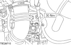
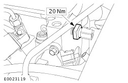
| * Oil cooler. | * INSTALL a new oil cooler. |
| * Damaged gaskets or warped mating faces. | * CHECK the cylinder head gasket for damage. CHECK the cylinder head for distortion. |
| * Cracks or fractures in engine components surrounded by coolant, such as cylinder liners and cylinder head combustion chamber. | * DETERMINE the damaged engine component(s) and install new component(s) as necessary. |
| Engine will not crank | * Battery or cables. | * CHECK the battery, bracket and cables.
REFER to: Battery (414-01 Battery, Mounting and Cables, Diagnosis and Testing).
|
| * Starter motor or cables. | * CHECK the starting system.
REFER to: Starting System (303-06A Starting System, Diagnosis and Testing).
|
| Engine cranks but will not start | * Fuel tank is empty. | * CHECK the fuel level. |
| * Water in fuel (only diesel engine). | * Drain the water from the fuel system. |
| * Fuel filter blocked. | * INSTALL a new fuel filter. REFER to: (310-01 Fuel Tank and Lines) Fuel Filter - 1.8L Duratec-HE (MI4)/2.0L Duratec-HE (MI4) (Removal and Installation), Fuel Filter - 1.6L Duratorq-TDCi (DV) Diesel (Removal and Installation), Fuel Filter - 2.0L Duratorq-TDCi (DW) Diesel, Vehicles With: Water-in-Fuel Sensor (Removal and Installation), Fuel Filter - 2.0L Duratorq-TDCi (DW) Diesel, Vehicles Without: Water-in-Fuel Sensor (Removal and Installation), Fuel Filter - 1.8L Duratorq-TDCi (Kent) Diesel, Vehicles Without: Water-in-Fuel Sensor (Removal and Installation). |
| * Engine intake air system. | * CHECK the intake air system.
REFER to: Intake Air Distribution and Filtering (303-12A Intake Air Distribution and Filtering, Diagnosis and Testing).
|
| * Glow plug faulty (only diesel engine). | * CHECK the glow plugs. INSTALL new glow plugs as necessary.
REFER to: Glow Plug System (303-07C Glow Plug System - 1.6L Duratorq-TDCi (DV) Diesel/2.0L Duratorq-TDCi (DW) Diesel, Diagnosis and Testing).
|
| * Engine management system. | * CHECK the engine management system.
REFER to: Electronic Engine Controls (303-14A Electronic Engine Controls, Diagnosis and Testing).
|
| * Ignition system (only petrol engines). | * CHECK the ignition system. Engine - 1.4L Duratec-16V (Sigma)/1.6L Duratec-16V (Sigma) -
REFER to: Engine Ignition (303-07A Engine Ignition - 1.4L Duratec-16V (Sigma)/1.6L Duratec-16V (Sigma)/1.6L Duratec-16V Ti-VCT (Sigma), Diagnosis and Testing).
Engine - 1.8L Duratec-HE (MI4)/2.0L Duratec-HE (MI4) -
REFER to: Engine Ignition (303-07B, Diagnosis and Testing).
Engine - 2.5L Duratec-ST (VI5) -
REFER to: Engine Ignition (303-07E, Diagnosis and Testing).
|
| * Incorrect valve timing. | * CHECK and adjust the valve timing. Engine - 1.4L Duratec-16V (Sigma)/1.6L Duratec-16V (Sigma) -
REFER to: Timing Belt - Vehicles Built Up To: 04/2005 (303-01A Engine - 1.4L Duratec-16V (Sigma)/1.6L Duratec-16V (Sigma), In-vehicle Repair).
Engine - 1.6L Duratec-16V Ti-VCT -
REFER to: Timing Belt (303-01B Engine - 1.6L Duratec-16V Ti-VCT (Sigma), In-vehicle Repair).
Engine - 1.8L Duratec-HE (MI4)/2.0L Duratec-HE (MI4) -
REFER to: Timing Chain (303-01C Engine - 1.8L Duratec-HE (MI4)/2.0L Duratec-HE (MI4), In-vehicle Repair).
Engine - 2.5L Duratec-ST (VI5) -
REFER to: Timing Belt (303-01D, Removal and Installation).
Engine - 1.6L Duratorq-TDCi (DV) Diesel -
REFER to: Timing Belt (303-01E Engine - 1.6L Duratorq-TDCi (DV) Diesel, In-vehicle Repair).
Engine - 1.8L Duratorq-TDCi (Kent) Diesel -
REFER to: Timing Belt (303-01F, In-vehicle Repair).
Engine - 2.0L Duratorq-TDCi (DW) Diesel -
REFER to: Timing Belt (303-01G Engine - 2.0L Duratorq-TDCi (DW) Diesel, In-vehicle Repair).
|
| * Broken or damaged timing belt/timing chain or pulley/sprocket. | * CHECK the timing belt/timing chain and sprockets/pulleys. INSTALL new components as necessary. Engine - 1.4L Duratec-16V (Sigma)/1.6L Duratec-16V (Sigma) -
REFER to: Timing Belt - Vehicles Built Up To: 04/2005 (303-01A Engine - 1.4L Duratec-16V (Sigma)/1.6L Duratec-16V (Sigma), In-vehicle Repair).
Engine - 1.6L Duratec-16V Ti-VCT -
REFER to: Timing Belt (303-01B Engine - 1.6L Duratec-16V Ti-VCT (Sigma), In-vehicle Repair).
Engine - 1.8L Duratec-HE (MI4)/2.0L Duratec-HE (MI4) -
REFER to: Timing Chain (303-01C Engine - 1.8L Duratec-HE (MI4)/2.0L Duratec-HE (MI4), In-vehicle Repair).
Engine - 2.5L Duratec-ST (VI5) -
REFER to: Timing Belt (303-01D, Removal and Installation).
Engine - 1.6L Duratorq-TDCi (DV) Diesel -
REFER to: Timing Belt (303-01E Engine - 1.6L Duratorq-TDCi (DV) Diesel, In-vehicle Repair).
Engine - 1.8L Duratorq-TDCi (Kent) Diesel -
REFER to: Timing Belt (303-01F, In-vehicle Repair).
Engine - 2.0L Duratorq-TDCi (DW) Diesel -
REFER to: Timing Belt (303-01G Engine - 2.0L Duratorq-TDCi (DW) Diesel, In-vehicle Repair).
|
| Very poor power output or fuel consumption too high or engine running rough. | * Fuel system. | * CHECK the fuel system. Engine - 1.4L Duratec-16V (Sigma)/1.6L Duratec-16V (Sigma) -
REFER to: Fuel Charging and Controls (303-04A Fuel Charging and Controls - 1.4L Duratec-16V (Sigma)/1.6L Duratec-16V (Sigma), Diagnosis and Testing).
Engine - 1.6L Duratec-16V Ti-VCT -
REFER to: Fuel Charging and Controls (303-04A Fuel Charging and Controls - 1.4L Duratec-16V (Sigma)/1.6L Duratec-16V (Sigma), Diagnosis and Testing).
Engine - 1.8L Duratec-HE (MI4)/2.0L Duratec-HE (MI4) -
REFER to: Fuel Charging and Controls (303-04C Fuel Charging and Controls - 1.8L Duratec-HE (MI4)/2.0L Duratec-HE (MI4), Diagnosis and Testing).
Engine - 2.5L Duratec-ST (VI5) -
REFER to: Fuel Charging and Controls (303-04D, Diagnosis and Testing).
Engine - 1.6L Duratorq-TDCi (DV) Diesel -
REFER to: Fuel Charging and Controls (303-04F Fuel Charging and Controls - 1.6L Duratorq-TDCi (DV) Diesel, Diagnosis and Testing).
Engine - 2.0L Duratorq-TDCi (DW) Diesel -
REFER to: Fuel Charging and Controls (303-04H Fuel Charging and Controls - 2.0L Duratorq-TDCi (DW) Diesel, Diagnosis and Testing).
Engine - 1.8L Duratorq-TDCi (Kent) Diesel -
REFER to: Fuel Charging and Controls - 1.8L Duratorq-TDCi (Kent) Diesel (303-04G Fuel Charging and Controls - 1.8L Duratorq-TDCi (Kent) Diesel, Diagnosis and Testing).
|
| * Engine intake air system. | * CHECK the intake air system.
REFER to: Intake Air Distribution and Filtering (303-12A Intake Air Distribution and Filtering, Diagnosis and Testing).
|
| * Exhaust system blocked. | * CHECK the exhaust system.
REFER to: Exhaust System (309-00A Exhaust System, Description and Operation).
|
| * Engine management system. | * CHECK the engine management system.
REFER to: Electronic Engine Controls (303-14A Electronic Engine Controls, Diagnosis and Testing).
|
| * Fault in ignition system (only petrol engines). | * CHECK the ignition system. Engine - 1.4L Duratec-16V (Sigma)/1.6L Duratec-16V (Sigma) -
REFER to: Engine Ignition (303-07A Engine Ignition - 1.4L Duratec-16V (Sigma)/1.6L Duratec-16V (Sigma)/1.6L Duratec-16V Ti-VCT (Sigma), Diagnosis and Testing).
Engine - 1.8L Duratec-HE (MI4)/2.0L Duratec-HE (MI4) -
REFER to: Engine Ignition (303-07E Engine Ignition - 2.5L Duratec-ST (VI5), Diagnosis and Testing).
Engine - 2.5L Duratec-ST (VI5) -
REFER to: Engine Ignition (303-07E, Diagnosis and Testing).
|
| * Turbocharger. | * CHECK the turbocharger. Engine - 2.5L Duratec-ST (VI5) -
REFER to: Turbocharger (303-04E, Removal and Installation) /
Turbocharger - 1.6L Duratorq-TDCi (DV) Diesel (303-04I Fuel Charging and Controls - Turbocharger, Diagnosis and Testing) /
Turbocharger - 2.0L Duratorq-TDCi (DW) Diesel (303-04I Fuel Charging and Controls - Turbocharger, Diagnosis and Testing) /
Turbocharger - 1.8L Duratorq-TDCi (Kent) Diesel (303-04I Fuel Charging and Controls - Turbocharger, Diagnosis and Testing).
|
| * Incorrect valve timing. Timing belt/timing sprocket or pulley/sprocket damaged. | * CHECK and adjust valve timing. INSTALL new components as necessary. Engine - 1.4L Duratec-16V (Sigma)/1.6L Duratec-16V (Sigma) -
REFER to: Timing Belt - Vehicles Built Up To: 04/2005 (303-01A Engine - 1.4L Duratec-16V (Sigma)/1.6L Duratec-16V (Sigma), In-vehicle Repair).
Engine - 1.6L Duratec-16V Ti-VCT -
REFER to: Timing Belt (303-01B Engine - 1.6L Duratec-16V Ti-VCT (Sigma), In-vehicle Repair).
Engine - 1.8L Duratec-HE (MI4)/2.0L Duratec-HE (MI4) -
REFER to: Timing Chain (303-01C Engine - 1.8L Duratec-HE (MI4)/2.0L Duratec-HE (MI4), In-vehicle Repair).
Engine - 2.5L Duratec-ST (VI5) -
REFER to: Timing Belt (303-01D, Removal and Installation).
Engine - 1.6L Duratorq-TDCi (DV) Diesel -
REFER to: Timing Belt (303-01E Engine - 1.6L Duratorq-TDCi (DV) Diesel, In-vehicle Repair).
Engine - 1.8L Duratorq-TDCi (Kent) Diesel -
REFER to: Timing Belt (303-01F, In-vehicle Repair).
Engine - 2.0L Duratorq-TDCi (DW) Diesel -
REFER to: Timing Belt (303-01G Engine - 2.0L Duratorq-TDCi (DW) Diesel, In-vehicle Repair).
|
| * Ignition timing incorrect (only petrol engines). | * CHECK the electronic engine controls.
REFER to: Electronic Engine Controls (303-14A Electronic Engine Controls, Diagnosis and Testing).
|
| Noisy running | * Engine auxiliary components loose or damaged. | * CHECK engine auxiliary components for damage or looseness. CHECK and adjust valve timing. INSTALL new components as necessary. Engine - 1.4L Duratec-16V (Sigma)/1.6L Duratec-16V (Sigma) -
REFER to: Timing Belt - Vehicles Built Up To: 04/2005 (303-01A Engine - 1.4L Duratec-16V (Sigma)/1.6L Duratec-16V (Sigma), In-vehicle Repair).
Engine - 1.6L Duratec-16V Ti-VCT -
REFER to: Timing Belt (303-01B Engine - 1.6L Duratec-16V Ti-VCT (Sigma), In-vehicle Repair).
Engine - 1.8L Duratec-HE (MI4)/2.0L Duratec-HE (MI4) -
REFER to: Timing Chain (303-01C Engine - 1.8L Duratec-HE (MI4)/2.0L Duratec-HE (MI4), In-vehicle Repair).
Engine - 2.5L Duratec-ST (VI5) -
REFER to: Timing Belt (303-01D, Removal and Installation).
Engine - 1.6L Duratorq-TDCi (DV) Diesel -
REFER to: Timing Belt (303-01E Engine - 1.6L Duratorq-TDCi (DV) Diesel, In-vehicle Repair).
Engine - 1.8L Duratorq-TDCi (Kent) Diesel -
REFER to: Timing Belt (303-01F, In-vehicle Repair).
Engine - 2.0L Duratorq-TDCi (DW) Diesel -
REFER to: Timing Belt (303-01G Engine - 2.0L Duratorq-TDCi (DW) Diesel, In-vehicle Repair).
|
| Noisy running, misfiring, backfiring or knocking | * Incorrect fuel | * DETERMINE which type of fuel was last put in the tank (note the country specific fuel specifications). |
| * Water in fuel or fuel contaminated. | * CHECK the fuel system for water or other contamination. |
| * Valve timing incorrect, timing belt/chain or pulley/sprocket damaged. | * CHECK and adjust valve timing. INSTALL new components as necessary. Engine - 1.4L Duratec-16V (Sigma)/1.6L Duratec-16V (Sigma) -
REFER to: Timing Belt - Vehicles Built Up To: 04/2005 (303-01A Engine - 1.4L Duratec-16V (Sigma)/1.6L Duratec-16V (Sigma), In-vehicle Repair).
Engine - 1.6L Duratec-16V Ti-VCT -
REFER to: Timing Belt (303-01B Engine - 1.6L Duratec-16V Ti-VCT (Sigma), In-vehicle Repair).
Engine - 1.8L Duratec-HE (MI4)/2.0L Duratec-HE (MI4) -
REFER to: Timing Chain (303-01C Engine - 1.8L Duratec-HE (MI4)/2.0L Duratec-HE (MI4), In-vehicle Repair).
Engine - 2.5L Duratec-ST (VI5) -
REFER to: Timing Belt (303-01D, Removal and Installation).
Engine - 1.6L Duratorq-TDCi (DV) Diesel -
REFER to: Timing Belt (303-01E Engine - 1.6L Duratorq-TDCi (DV) Diesel, In-vehicle Repair).
Engine - 1.8L Duratorq-TDCi (Kent) Diesel -
REFER to: Timing Belt (303-01F, In-vehicle Repair).
Engine - 2.0L Duratorq-TDCi (DW) Diesel -
REFER to: Timing Belt (303-01G Engine - 2.0L Duratorq-TDCi (DW) Diesel, In-vehicle Repair).
|
| Noisy running or valve train noise | * Valve clearance too large due to faulty valve tappets or worn valve train components. | * INSTALL new hydraulic lash adjusters or adjust the valve clearance. Engine - 1.4L Duratec-16V (Sigma)/1.6L Duratec-16V (Sigma) -
REFER to: Valve Clearance Adjustment (303-01A Engine - 1.4L Duratec-16V (Sigma)/1.6L Duratec-16V (Sigma), General Procedures).
Engine - 1.6L Duratec-16V Ti-VCT -
REFER to: Valve Clearance Adjustment (303-01B Engine - 1.6L Duratec-16V Ti-VCT (Sigma), General Procedures).
Engine - 1.8L Duratec-HE (MI4)/2.0L Duratec-HE (MI4) -
REFER to: Valve Clearance Adjustment (303-01C, General Procedures).
Engine - 2.5L Duratec-ST (VI5) -
REFER to: Valve Clearance Adjustment (303-01D, General Procedures).
Engine - 1.6L Duratorq-TDCi (DV) Diesel -
REFER to: Camshaft (303-01E Engine - 1.6L Duratorq-TDCi (DV) Diesel, In-vehicle Repair).
Engine - 2.0L Duratorq-TDCi (DW) Diesel -
REFER to: Camshafts (303-01G Engine - 2.0L Duratorq-TDCi (DW) Diesel, In-vehicle Repair).
Engine - 1.8L Duratorq-TDCi (Kent) Diesel -
REFER to: Camshafts (303-01F Engine - 1.8L Duratorq-TDCi (Kent) Diesel, In-vehicle Repair).
|
| * Timing belt or timing chain damaged. | * INSTALL a new timing belt or timing chain. Engine - 1.4L Duratec-16V (Sigma)/1.6L Duratec-16V (Sigma) -
REFER to: Timing Belt - Vehicles Built Up To: 04/2005 (303-01A Engine - 1.4L Duratec-16V (Sigma)/1.6L Duratec-16V (Sigma), In-vehicle Repair).
Engine - 1.6L Duratec-16V Ti-VCT -
REFER to: Timing Belt (303-01B Engine - 1.6L Duratec-16V Ti-VCT (Sigma), In-vehicle Repair).
Engine - 1.8L Duratec-HE (MI4)/2.0L Duratec-HE (MI4) -
REFER to: Timing Chain (303-01C Engine - 1.8L Duratec-HE (MI4)/2.0L Duratec-HE (MI4), In-vehicle Repair).
Engine - 2.5L Duratec-ST (VI5) -
REFER to: Timing Belt (303-01D, Removal and Installation).
Engine - 1.6L Duratorq-TDCi (DV) Diesel -
REFER to: Timing Belt (303-01E Engine - 1.6L Duratorq-TDCi (DV) Diesel, In-vehicle Repair).
Engine - 1.8L Duratorq-TDCi (Kent) Diesel -
REFER to: Timing Belt (303-01F, In-vehicle Repair).
Engine - 2.0L Duratorq-TDCi (DW) Diesel -
REFER to: Timing Belt (303-01G Engine - 2.0L Duratorq-TDCi (DW) Diesel, In-vehicle Repair).
|
| * Timing belt or timing chain incorrectly tensioned. | * CHECK the timing belt tension. INSTALL a new timing belt or timing chain as necessary. Engine - 1.4L Duratec-16V (Sigma)/1.6L Duratec-16V (Sigma) -
REFER to: Timing Belt - Vehicles Built Up To: 04/2005 (303-01A Engine - 1.4L Duratec-16V (Sigma)/1.6L Duratec-16V (Sigma), In-vehicle Repair).
Engine - 1.6L Duratec-16V Ti-VCT -
REFER to: Timing Belt (303-01B Engine - 1.6L Duratec-16V Ti-VCT (Sigma), In-vehicle Repair).
Engine - 1.8L Duratec-HE (MI4)/2.0L Duratec-HE (MI4) -
REFER to: Timing Chain (303-01C Engine - 1.8L Duratec-HE (MI4)/2.0L Duratec-HE (MI4), In-vehicle Repair).
Engine - 2.5L Duratec-ST (VI5) -
REFER to: Timing Belt (303-01D, Removal and Installation).
Engine - 1.6L Duratorq-TDCi (DV) Diesel -
REFER to: Timing Belt (303-01E Engine - 1.6L Duratorq-TDCi (DV) Diesel, In-vehicle Repair).
Engine - 1.8L Duratorq-TDCi (Kent) Diesel -
REFER to: Timing Belt (303-01F, In-vehicle Repair).
Engine - 2.0L Duratorq-TDCi (DW) Diesel -
REFER to: Timing Belt (303-01G Engine - 2.0L Duratorq-TDCi (DW) Diesel, In-vehicle Repair).
|
| Noisy running or engine noise | * Engine components - Pistons. - Piston rings. - Connecting rod big end, main bearing or thrust bearing journals. - Connecting rods bent or damaged. | * CHECK the engine components for wear or damage. Make sure all components are within specification. INSTALL new components as necessary. Engine - 1.4L Duratec-16V (Sigma)/1.6L Duratec-16V (Sigma) -
REFER to: Specifications (303-01A Engine - 1.4L Duratec-16V (Sigma)/1.6L Duratec-16V (Sigma), Specifications).
Engine - 1.6L Duratec-16V Ti-VCT -
REFER to: Specifications (303-01B Engine - 1.6L Duratec-16V Ti-VCT (Sigma), Specifications).
Engine - 1.8L Duratec-HE (MI4)/2.0L Duratec-HE (MI4) -
REFER to: Specifications (303-01C, Specifications).
Engine - 1.6L Duratorq-TDCi (DV) Diesel -
REFER to: Specifications (303-01A, Specifications).
Engine - 1.8L Duratorq-TDCi (Kent) Diesel -
REFER to: Specifications (303-01F, Specifications).
Engine - 2.0L Duratorq-TDCi (DW) Diesel -
REFER to: Specifications (303-01G, Specifications).
|