| Symptom | Possible Sources | Action |
| Engine cranks but does not start | * Fuel charging and controls. | * Vehicles with 1.6L Duratorq-TDCi (DV) diesel engine.
REFER to: Fuel Charging and Controls (303-04D, Diagnosis and Testing).
Vehicles with 1.8L Duratorq-TDCi (Kent) diesel engine.
REFER to: Fuel Charging and Controls - 1.8L Duratorq-TDCi (Kent) Diesel (303-04G, Diagnosis and Testing).
Vehicles with 2.0L Duratorq-TDCi (DW) diesel engine.
REFER to: Fuel Charging and Controls (303-04E, Diagnosis and Testing).
|
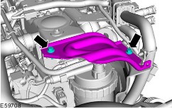
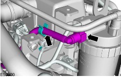
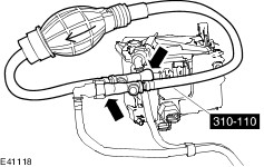
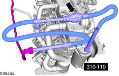
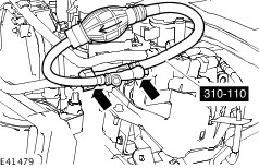
| * Air ingress into the fuel lines. | * Vehicles with 1.6L Duratorq-TDCi (DV) diesel engine. GO to Pinpoint Test A. Vehicles with 1.8L Duratorq-TDCi (Kent) diesel engine. GO to Pinpoint Test B. Vehicles with 2.0L Duratorq-TDCi (DW) diesel engine. GO to Pinpoint Test C. |
| * Contaminated fuel. | * INSTALL a new fuel filter.
REFER to: Fuel Filter - 1.6L Duratorq-TDCi (DV) Diesel (310-01, Removal and Installation) /
Fuel Filter - 1.8L Duratorq-TDCi (Kent) Diesel, Vehicles Without: Water-in-Fuel Sensor (310-01, Removal and Installation) /
Fuel Filter - 2.0L Duratorq-TDCi (DW) Diesel, Vehicles With: Water-in-Fuel Sensor (310-01, Removal and Installation).
or
REFER to: Fuel Filter - 2.0L Duratorq-TDCi (DW) Diesel, Vehicles Without: Water-in-Fuel Sensor (310-01, Removal and Installation).
DRAIN and INSTALL new fuel.
REFER to: Fuel Tank - 1.6L Duratorq-TDCi (DV) Diesel/2.0L Duratorq-TDCi (DW) Diesel, Vehicles With: Fuel Additive Tank (310-01, Removal and Installation).
or
REFER to: Fuel Tank - 1.6L Duratorq-TDCi (DV) Diesel/2.0L Duratorq-TDCi (DW) Diesel, Vehicles Without: Fuel Additive Tank (310-01, Removal and Installation).
|
| Poor starting | * Fuel charging and controls. | * Vehicles with 1.6L Duratorq-TDCi (DV) diesel engine.
REFER to: Fuel Charging and Controls (303-04D, Diagnosis and Testing).
Vehicles with 1.8L Duratorq-TDCi (Kent) diesel engine.
REFER to: Fuel Charging and Controls - 1.8L Duratorq-TDCi (Kent) Diesel (303-04G, Diagnosis and Testing).
Vehicles with 2.0L Duratorq-TDCi (DW) diesel engine.
REFER to: Fuel Charging and Controls (303-04E, Diagnosis and Testing).
|
| * Air ingress into the fuel lines. | * Vehicles with 1.6L Duratorq-TDCi (DV) diesel engine. GO to Pinpoint Test A. Vehicles with 1.8L Duratorq-TDCi (Kent) diesel engine. GO to Pinpoint Test B. Vehicles with 2.0L Duratorq-TDCi (DW) diesel engine. GO to Pinpoint Test C. |
| * Contaminated fuel. | * INSTALL a new fuel filter.
REFER to: Fuel Filter - 1.6L Duratorq-TDCi (DV) Diesel (310-01, Removal and Installation) /
Fuel Filter - 1.8L Duratorq-TDCi (Kent) Diesel, Vehicles Without: Water-in-Fuel Sensor (310-01, Removal and Installation) /
Fuel Filter - 2.0L Duratorq-TDCi (DW) Diesel, Vehicles With: Water-in-Fuel Sensor (310-01, Removal and Installation).
or
REFER to: Fuel Filter - 2.0L Duratorq-TDCi (DW) Diesel, Vehicles Without: Water-in-Fuel Sensor (310-01, Removal and Installation).
DRAIN and INSTALL new fuel.
REFER to: Fuel Tank - 1.6L Duratorq-TDCi (DV) Diesel/2.0L Duratorq-TDCi (DW) Diesel, Vehicles With: Fuel Additive Tank (310-01, Removal and Installation).
or
REFER to: Fuel Tank - 1.6L Duratorq-TDCi (DV) Diesel/2.0L Duratorq-TDCi (DW) Diesel, Vehicles Without: Fuel Additive Tank (310-01, Removal and Installation).
|
| Engine starts but immediately stops | * Fuel charging and controls. | * Vehicles with 1.6L Duratorq-TDCi (DV) diesel engine.
REFER to: Fuel Charging and Controls (303-04D, Diagnosis and Testing).
Vehicles with 1.8L Duratorq-TDCi (Kent) diesel engine.
REFER to: Fuel Charging and Controls - 1.8L Duratorq-TDCi (Kent) Diesel (303-04G, Diagnosis and Testing).
Vehicles with 2.0L Duratorq-TDCi (DW) diesel engine.
REFER to: Fuel Charging and Controls (303-04E, Diagnosis and Testing).
|
| * Air ingress into the fuel lines. | * Vehicles with 1.6L Duratorq-TDCi (DV) diesel engine. GO to Pinpoint Test A. Vehicles with 1.8L Duratorq-TDCi (Kent) diesel engine. GO to Pinpoint Test B. Vehicles with 2.0L Duratorq-TDCi (DW) diesel engine. GO to Pinpoint Test C. |
| Poor idling | * Fuel charging and controls. | * Vehicles with 1.6L Duratorq-TDCi (DV) diesel engine.
REFER to: Fuel Charging and Controls (303-04D, Diagnosis and Testing).
Vehicles with 1.8L Duratorq-TDCi (Kent) diesel engine.
REFER to: Fuel Charging and Controls - 1.8L Duratorq-TDCi (Kent) Diesel (303-04G, Diagnosis and Testing).
Vehicles with 2.0L Duratorq-TDCi (DW) diesel engine.
REFER to: Fuel Charging and Controls (303-04E, Diagnosis and Testing).
|
| * Air ingress into the fuel lines. | * Vehicles with 1.6L Duratorq-TDCi (DV) diesel engine. GO to Pinpoint Test A. Vehicles with 1.8L Duratorq-TDCi (Kent) diesel engine. GO to Pinpoint Test B. Vehicles with 2.0L Duratorq-TDCi (DW) diesel engine. GO to Pinpoint Test C. |
| * Contaminated fuel. | * INSTALL a new fuel filter.
REFER to: Fuel Filter - 1.6L Duratorq-TDCi (DV) Diesel (310-01, Removal and Installation) /
Fuel Filter - 1.8L Duratorq-TDCi (Kent) Diesel, Vehicles Without: Water-in-Fuel Sensor (310-01, Removal and Installation) /
Fuel Filter - 2.0L Duratorq-TDCi (DW) Diesel, Vehicles With: Water-in-Fuel Sensor (310-01, Removal and Installation).
or
REFER to: Fuel Filter - 2.0L Duratorq-TDCi (DW) Diesel, Vehicles Without: Water-in-Fuel Sensor (310-01, Removal and Installation).
DRAIN and INSTALL new fuel.
REFER to: Fuel Tank - 1.6L Duratorq-TDCi (DV) Diesel/2.0L Duratorq-TDCi (DW) Diesel, Vehicles With: Fuel Additive Tank (310-01, Removal and Installation).
or
REFER to: Fuel Tank - 1.6L Duratorq-TDCi (DV) Diesel/2.0L Duratorq-TDCi (DW) Diesel, Vehicles Without: Fuel Additive Tank (310-01, Removal and Installation).
|
| Engine lacks power | * Fuel tank to fuel filter fuel supply line blocked. | * CHECK the fuel supply lines for damage. INSTALL a new fuel filter fuel supply line.
REFER to: Fuel Supply Line - 1.6L Duratorq-TDCi (DV) Diesel/2.0L Duratorq-TDCi (DW) Diesel (310-01, Removal and Installation).
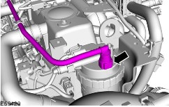
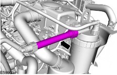
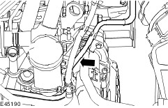
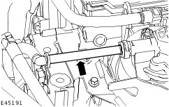
* CHECK the fuel supply line for blockage. Vehicles with 1.6L Duratorq-TDCi (DV) diesel engine. GO to Pinpoint Test D. Vehicles with 1.8L Duratorq-TDCi (Kent) diesel engine. GO to Pinpoint Test E. Vehicles with 2.0L Duratorq-TDCi (DW) diesel engine. GO to Pinpoint Test F. |
| * Fuel filter blocked. | * INSTALL a new fuel filter.
REFER to: Fuel Filter - 1.6L Duratorq-TDCi (DV) Diesel (310-01, Removal and Installation) /
Fuel Filter - 1.8L Duratorq-TDCi (Kent) Diesel, Vehicles Without: Water-in-Fuel Sensor (310-01, Removal and Installation) /
Fuel Filter - 2.0L Duratorq-TDCi (DW) Diesel, Vehicles With: Water-in-Fuel Sensor (310-01, Removal and Installation).
or
REFER to: Fuel Filter - 2.0L Duratorq-TDCi (DW) Diesel, Vehicles Without: Water-in-Fuel Sensor (310-01, Removal and Installation).
|
| * Fuel charging and controls. | * Vehicles with 1.6L Duratorq-TDCi (DV) diesel engine.
REFER to: Fuel Charging and Controls (303-04D, Diagnosis and Testing).
Vehicles with 1.8L Duratorq-TDCi (Kent) diesel engine.
REFER to: Fuel Charging and Controls - 1.8L Duratorq-TDCi (Kent) Diesel (303-04G, Diagnosis and Testing).
Vehicles with 2.0L Duratorq-TDCi (DW) diesel engine.
REFER to: Fuel Charging and Controls (303-04E, Diagnosis and Testing).
|
| * Air ingress into the fuel lines. | * Vehicles with 1.6L Duratorq-TDCi (DV) diesel engine. GO to Pinpoint Test A. Vehicles with 1.8L Duratorq-TDCi (Kent) diesel engine. GO to Pinpoint Test B. Vehicles with 2.0L Duratorq-TDCi (DW) diesel engine. GO to Pinpoint Test C. |
| * Contaminated fuel. | * INSTALL a new fuel filter.
REFER to: Fuel Filter - 1.6L Duratorq-TDCi (DV) Diesel (310-01, Removal and Installation) /
Fuel Filter - 1.8L Duratorq-TDCi (Kent) Diesel, Vehicles Without: Water-in-Fuel Sensor (310-01, Removal and Installation) /
Fuel Filter - 2.0L Duratorq-TDCi (DW) Diesel, Vehicles With: Water-in-Fuel Sensor (310-01, Removal and Installation).
or
REFER to: Fuel Filter - 2.0L Duratorq-TDCi (DW) Diesel, Vehicles Without: Water-in-Fuel Sensor (310-01, Removal and Installation).
DRAIN and INSTALL new fuel.
REFER to: Fuel Tank - 1.6L Duratorq-TDCi (DV) Diesel/2.0L Duratorq-TDCi (DW) Diesel, Vehicles With: Fuel Additive Tank (310-01, Removal and Installation).
or
REFER to: Fuel Tank - 1.6L Duratorq-TDCi (DV) Diesel/2.0L Duratorq-TDCi (DW) Diesel, Vehicles Without: Fuel Additive Tank (310-01, Removal and Installation).
|
| Engine misfire | * Fuel charging and controls. | * Vehicles with 1.6L Duratorq-TDCi (DV) diesel engine.
REFER to: Fuel Charging and Controls (303-04D, Diagnosis and Testing).
Vehicles with 1.8L Duratorq-TDCi (Kent) diesel engine.
REFER to: Fuel Charging and Controls - 1.8L Duratorq-TDCi (Kent) Diesel (303-04G, Diagnosis and Testing).
Vehicles with 2.0L Duratorq-TDCi (DW) diesel engine.
REFER to: Fuel Charging and Controls (303-04E, Diagnosis and Testing).
|
| * Air ingress into the fuel lines. | * Vehicles with 1.6L Duratorq-TDCi (DV) diesel engine. GO to Pinpoint Test A. Vehicles with 1.8L Duratorq-TDCi (Kent) diesel engine. GO to Pinpoint Test B. Vehicles with 2.0L Duratorq-TDCi (DW) diesel engine. GO to Pinpoint Test C. |
| Excessive fuel consumption | * Fuel charging and controls. | * Vehicles with 1.6L Duratorq-TDCi (DV) diesel engine.
REFER to: Fuel Charging and Controls (303-04D, Diagnosis and Testing).
Vehicles with 1.8L Duratorq-TDCi (Kent) diesel engine.
REFER to: Fuel Charging and Controls - 1.8L Duratorq-TDCi (Kent) Diesel (303-04G, Diagnosis and Testing).
Vehicles with 2.0L Duratorq-TDCi (DW) diesel engine.
REFER to: Fuel Charging and Controls (303-04E, Diagnosis and Testing).
|
| * Air ingress into the fuel lines. | * Vehicles with 1.6L Duratorq-TDCi (DV) diesel engine. GO to Pinpoint Test A. Vehicles with 1.8L Duratorq-TDCi (Kent) diesel engine. GO to Pinpoint Test B. Vehicles with 2.0L Duratorq-TDCi (DW) diesel engine. GO to Pinpoint Test C. |
| * Contaminated fuel. | * INSTALL a new fuel filter.
REFER to: Fuel Filter - 1.6L Duratorq-TDCi (DV) Diesel (310-01, Removal and Installation) /
Fuel Filter - 1.8L Duratorq-TDCi (Kent) Diesel, Vehicles Without: Water-in-Fuel Sensor (310-01, Removal and Installation) /
Fuel Filter - 2.0L Duratorq-TDCi (DW) Diesel, Vehicles With: Water-in-Fuel Sensor (310-01, Removal and Installation).
or
REFER to: Fuel Filter - 2.0L Duratorq-TDCi (DW) Diesel, Vehicles Without: Water-in-Fuel Sensor (310-01, Removal and Installation).
DRAIN and INSTALL new fuel.
REFER to: Fuel Tank - 1.6L Duratorq-TDCi (DV) Diesel/2.0L Duratorq-TDCi (DW) Diesel, Vehicles With: Fuel Additive Tank (310-01, Removal and Installation).
or
REFER to: Fuel Tank - 1.6L Duratorq-TDCi (DV) Diesel/2.0L Duratorq-TDCi (DW) Diesel, Vehicles Without: Fuel Additive Tank (310-01, Removal and Installation).
|
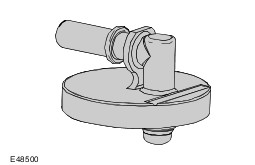
| Fuel filler nozzle shuts off prematurely | * Fuel tank ventilation hose or pipe blocked. * Fuel tank ventilation hose or pipe collapsed. | * CHECK the fuel tank ventilation hose for obstruction or damage. INSTALL a new fuel tank ventilation pipe. for additional information,
REFER to: Fuel Tank Filler Pipe (310-01, Removal and Installation).
|
| * Fuel tank filler pipe or hose blocked. * Fuel tank filler pipe or hose collapsed. | * CHECK the fuel tank filler pipe or hose for obstruction or damage. INSTALL a new fuel tank filler pipe. for additional information,
REFER to: Fuel Tank Filler Pipe (310-01, Removal and Installation).
|
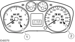
| * Fuel gauge indication. | * CHECK the fuel level in the fuel tank. CHECK the fuel indication system. For additional information,
REFER to: Instrument Cluster (413-01, Diagnosis and Testing).
|
| * Fuel filler nozzle at fuel filling station not functioning correctly. | * VERIFY condition by using a known good fuel filler nozzle. |
| Fuel loss after nozzle shutoff or during refilling | * Fuel tank filler pipe or hose leaking. | * CHECK the fuel tank filler pipe and hose for evidence of a fuel leak. If a fuel leak is evident, INSTALL a new fuel tank filler pipe and hose. For additional information,
REFER to: Fuel Tank Filler Pipe (310-01, Removal and Installation).
|
| * Fuel tank leaking. | * CHECK the fuel tank for evidence of a fuel leak. If a fuel leak is evident, INSTALL a new fuel tank. For additional information,
REFER to: Fuel Tank - 1.6L Duratorq-TDCi (DV) Diesel/2.0L Duratorq-TDCi (DW) Diesel, Vehicles With: Fuel Additive Tank (310-01, Removal and Installation).
or
REFER to: Fuel Tank - 1.6L Duratorq-TDCi (DV) Diesel/2.0L Duratorq-TDCi (DW) Diesel, Vehicles Without: Fuel Additive Tank (310-01, Removal and Installation).
|
| * Fuel tank ventilation pipe or hose leaking. | * CHECK the fuel tank ventilation pipe and hose for evidence of a fuel leak. If a fuel leak is evident, INSTALL a new fuel tank ventilation pipe and hose. For additional information,
REFER to: Fuel Tank Filler Pipe (310-01, Removal and Installation).
|