| Removal and Installation Removal NOTE:Removal steps in this procedure may contain installation details. NOTE:Four guide bolts (M10 x 120 mm) are required for removal of the dash panel together with the dash panel crossmember. | | -
Raise the vehicle. Refer to: Lifting (100-02 Jacking and Lifting, Description and Operation). | | | -
Remove the instrument panel. Refer to: Armaturenbrett - 3-Türer (501-12 Armaturenbrett und Konsole, Removal and Installation). | | | -
Remove the rubber seal from the head rail. Refer to: Header Rail Trim Panel (501-18 Convertible Top, Removal and Installation). | | | -
Remove the right and left-hand front seats. Refer to: Front Seat (501-10 Seating, Removal and Installation). | | | -
Remove the left and right-hand A-pillar trim. Refer to: A-Pillar Trim Panel (501-05 Interior Trim and Ornamentation, Removal and Installation). | | | -
Remove the left and right-hand rear side trim. Refer to: Rear Quarter Trim Panel - Convertible (501-05 Interior Trim and Ornamentation, Removal and Installation). | | | -
Remove the left and right-hand trim of the luggage compartment. Refer to: Loadspace Trim Panel - Convertible (501-05 Interior Trim and Ornamentation, Removal and Installation). | | | -
CAUTION:Make sure that the windshield wiper motor is in the park position. | | | -
WARNING:Make sure that new bolts are installed. | | | -
-
WARNING:Make sure that a new bolt is installed. Torque: 28 Nm | | | -
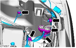
After removing the outer bolts of the dashboard crossmember, screw in two M10 x 120 mm guide bolts each into the right and left-hand A-pillars (shown without dashboard for a clearer view). | | | -
Pull the dashboard crossmember forwards until it reaches a stop. | Vehicles with automatic temperature control (EATC) All vehicles Installation CAUTION:Move the windshield wiper motor to the parked position before installing the wiper arms. | | -
NOTE:Connect a new passenger compartment wiring harness to the disconnected connector of the fuel pump module. Disconnect the fuel pump module connector from the new wiring harness. | | | -
-
Stripped ends of the wires | | | -
CAUTION:When crimping the connector ensure that the cross section of the connector matches that of the cable, and that the associated opening of the crimping pliers is used. NOTE:After crimping the connection, test it by performing a pull test. | | | -
NOTE:Using the hot air blower, heat the shrink sleeving of the crimp connector until the sleeving is tight on the connection and sealant emerges from each end. | | | -
Align the dashboard crossmember to the A-pillars (left-hand side shown). | | | -
To install, reverse the removal procedure. | |