| Diagnosis and Testing Refer to Wiring Diagrams Section 501-10, for schematic and connector information. Inspection and Verification - Verify the customer concern.
- Visually inspect for obvious signs of mechanical or electrical damage.
Visual Inspection Chart | Mechanical | Electrical | | | - Fuse(s)
- Wiring harness
- Electrical connector(s)
- Motor(s)
- Switch(es)
| - If an obvious cause for an observed or reported concern is found, correct the cause (if possible) before proceeding to the next step.
- If the cause is not visually evident, verify the symptom and refer to the Symptom Chart.
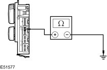
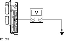
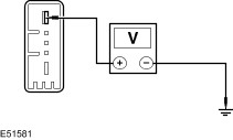
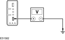
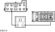
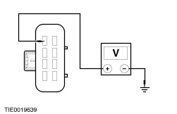
Symptom Chart Symptom Chart | Symptom | Possible Sources | Action | | The power seat is inoperative | * Seat control switch. | * CARRY OUT the Seat Control Switch Component Test. REFER to the Wiring Diagrams. | | * Motor(s). * Circuit(s). | * | | The power seat does not move vertically | * Seat control switch. | * CARRY OUT the Seat Control Switch Component Test. REFER to the Wiring Diagrams. | | * Motor(s). * Circuit(s). | * | | The power seat does not recline | * Seat control switch. | * CARRY OUT the Seat Control Switch Component Test. REFER to the Wiring Diagrams. | | * Motor. * Circuit(s). | * | | The power seat does not move horizontally | * Seat control switch. | * CARRY OUT the Seat Control Switch Component Test. REFER to the Wiring Diagrams. | | * Motor. * Circuit(s). | * | | The heated seat is inoperative | * Heated seat control switch(es). | * CARRY OUT the Heated Seat Control Switch Component Test. REFER to the Wiring Diagrams. | | * Circuit(s). | * | Pinpoint Tests NOTE:Use a digital multimeter for all electrical measurements. | PINPOINT TEST A : THE POWER SEAT IS INOPERATIVE | | TEST CONDITIONS | DETAILS/RESULTS/ACTIONS | | A1: CHECK FOR VOLTAGE TO THE DRIVER POWER SEAT | | | 1 Disconnect Driver Power Seat Underseat Connector C30. | | | 2 Ignition switch in position II. | | | 3 Measure the voltage between the driver power seat C30 pin 15, circuit 29-AH35 (OG/YE), harness side and ground. | | | Is the voltage greater than 10 volts? Yes No REPAIR circuit 29-AH35 (OG/YE). TEST the system for normal operation. | | A2: CHECK THE DRIVER POWER SEAT GROUND CIRCUIT FOR CONTINUITY | | | 1 Ignition switch in position 0. | | | 2 Measure the resistance between the driver power seat C30 pin 16, circuit 31-DA14 (BK), harness side and ground. | | | Is the resistance less than 5 ohms? Yes Vehicles with 6-way power seats GO to A3. Vehicles with 2-way power seats GO to A5. No REPAIR circuit 31-DA14 (BK). TEST the system for normal operation. | | A3: CHECK THE DRIVER POWER SEAT CONTROL SWITCH GROUND CIRCUIT FOR CONTINUITY | | | 1 Connect Driver Power Seat Underseat Connector C30. | | | 2 Disconnect Driver Power Seat Control Switch C755. | | | 3 Measure the resistance between the driver power seat control switch C755 pin 1, circuit 31-DA14 (BK), harness side and ground. | | | Is the resistance less than 5 ohms? Yes No REPAIR circuit 31-DA14 (BK). TEST the system for normal operation. | | A4: CHECK THE DRIVER POWER SEAT CONTROL SWITCH POWER CIRCUIT FOR CONTINUITY | | | 1 Ignition switch in position II. | | | 2 Measure the voltage between the driver power seat control switch C755 pin 2, circuit 29-AH35 (OG/YE), harness side and ground. | | | Is the voltage greater than 10 volts? Yes VERIFY the customer concern. No REPAIR circuit 29-AH35 (OG/YE). TEST the system for normal operation. | | A5: CHECK THE DRIVER POWER SEAT CONTROL SWITCH GROUND CIRCUIT FOR CONTINUITY | | | 1 Connect Driver Power Seat Underseat Connector C30. | | | 2 Disconnect Driver Power Seat Control Switch C715. | | | 3 Measure the resistance between the: - driver power seat control switch C715 pin 3, circuit 31-AH35 (BK), harness side and ground.
- driver power seat control switch C715 pin 6, circuit 31-AH35A (BK), harness side and ground.
| | | Are the resistances less than 5 ohms? Yes No REPAIR circuit 31-AH35 (BK) or circuit 31-AH35A (BK). TEST the system for normal operation. | | A6: CHECK THE DRIVER POWER SEAT CONTROL SWITCH POWER CIRCUIT FOR CONTINUITY | | | 1 Ignition switch in position II. | | | 2 Measure the voltage between the driver power seat control switch C715 pin 2, circuit 29-AH35 (OG/YE), harness side and ground. | | | Is the voltage greater than 10 volts? Yes VERIFY the customer concern. No REPAIR circuit 29-AH35 (OG/YE). TEST the system for normal operation. | | PINPOINT TEST B : THE POWER SEAT DOES NOT MOVE VERTICALLY | | TEST CONDITIONS | DETAILS/RESULTS/ACTIONS | | B1: CHECK THE DOWN VOLTAGE TO THE SEAT HEIGHT ADJUSTMENT MOTOR | | | 1 Detach the seat assembly from the floor panel. | | | 2 Disconnect Seat Height Adjustment Motor C759. | | | 3 Ignition switch in position II. | | | 4 Operate the power seat height control switch to the DOWN position and measure the voltage between the seat height adjustment motor C759 pin 1, circuit 33-AH38 (YE/BK), harness side and ground. | | | Is the voltage greater than 10 volts? Yes No REPAIR circuit 33-AH38 (YE/BK). TEST the system for normal operation. | | B2: CHECK THE UP VOLTAGE TO THE SEAT HEIGHT ADJUSTMENT MOTOR | | | 1 Operate the power seat height control switch to the UP position and measure the voltage between the seat height adjustment motor C759 pin 2, circuit 32-AH38 (WH/BK), harness side and ground. | | | Is the voltage greater than 10 volts? Yes INSTALL a new front seat height adjustment motor.
REFER to: Front Seat Height Adjustment Motor (501-10 Seating, Removal and Installation).
TEST the system for normal operation. No REPAIR circuit 32-AH38 (WH/BK). TEST the system for normal operation. | | PINPOINT TEST C : THE POWER SEAT DOES NOT RECLINE | | TEST CONDITIONS | DETAILS/RESULTS/ACTIONS | | C1: CHECK THE REARWARD VOLTAGE TO THE SEAT BACKREST MOVEMENT MOTOR | | | 1 Detach the seat assembly from the floor panel. | | | 2 Disconnect Seat Backrest Motor C760. | | | 3 Ignition switch in position II. | | | 4 Operate the power seat backrest control switch to the REARWARD position and measure the voltage between the seat backrest movement motor C760 pin 5, circuit 33-AH36 (YE/RD), harness side and ground. | | | Is the voltage greater than 10 volts? Yes No REPAIR circuit 33-AH36 (YE/RD). TEST the system for normal operation. | | C2: CHECK THE FORWARD VOLTAGE TO THE SEAT BACKREST MOVEMENT MOTOR | | | 1 Operate the power seat backrest control switch to the FORWARD position and measure the voltage between the seat backrest movement motor C760 pin 1, circuit 32-AH36 (WH/RD), harness side and ground. | | | Is the voltage greater than 10 volts? Yes INSTALL a new seat backrest movement motor.
REFER to: Front Seat Backrest - 3-Door (501-10 Seating, Disassembly and Assembly) /
Front Seat Backrest - 5-Door (501-10 Seating, Disassembly and Assembly).
TEST the system for normal operation. No REPAIR circuit 32-AH36 (WH/RD). TEST the system for normal operation. | | PINPOINT TEST D : THE POWER SEAT DOES NOT MOVE HORIZONTALLY | | TEST CONDITIONS | DETAILS/RESULTS/ACTIONS | | D1: CHECK THE REARWARD VOLTAGE TO THE FRONT SEAT TRACK MOTOR | | | 1 Detach the seat assembly from the floor panel. | | | 2 Disconnect Front Seat Track Motor C761. | | | 3 Ignition switch in position II. | | | 4 Operate the front seat track motor control switch to the REARWARD position and measure the voltage between the front seat track motor C761 pin 1, circuit 33-AH37 (YE/GN), harness side and ground. | | | Is the voltage greater than 10 volts? Yes No REPAIR circuit 33-AH37 (YE/GN). TEST the system for normal operation. | | D2: CHECK THE FORWARD VOLTAGE TO THE FRONT SEAT TRACK MOTOR | | | 1 Operate the front seat track motor control switch to the FORWARD position and measure the voltage between the front seat track motor C761 pin 5, circuit 32-AH37 (WH/GN), harness side and ground. | | | Is the voltage greater than 10 volts? Yes INSTALL a new front seat track motor.
REFER to: Front Seat Track Motor (501-10 Seating, Removal and Installation).
TEST the system for normal operation. No REPAIR circuit 32-AH37 (WH/GN). TEST the system for normal operation. | | PINPOINT TEST E : THE HEATED SEAT IS INOPERATIVE | | TEST CONDITIONS | DETAILS/RESULTS/ACTIONS | | E1: CHECK THE INOPERATIVE HEATED SEAT GROUND CIRCUIT | | | 1 Disconnect Inoperative Heated Seat C30 or C31. | | | 2 Measure the resistance between the: - Left-hand drive vehicles
- driver heated seat C30 pin 10, circuit 31-HC8 (BK), harness side and ground.
- passenger heated seat C31 pin 10, circuit 31-HC11 (BK), harness side and ground.
- Right-hand drive vehicles
- driver heated seat C30 pin 10, circuit 31-HC11 (BK), harness side and ground.
- passenger heated seat C31 pin 10, circuit 31-HC8 (BK), harness side and ground.
| | | Is the resistance less than 5 ohms? Yes No REPAIR circuit 31-HC8 (BK) or circuit 31-HC11 (BK). TEST the system for normal operation. | | E2: CHECK FOR BATTERY VOLTAGE TO THE INOPERATIVE HEATED SEAT | | | 1 Ignition switch in position II. | | | 2 Measure the voltage between the: - Left-hand drive vehicles
- driver heated seat C30 pin 9, circuit 15-HC8 (GN/RD), harness side and ground.
- passenger heated seat C31 pin 9, circuit 15-HC11 (GN/WH), harness side and ground.
- Right-hand drive vehicles
- driver heated seat C30 pin 9, circuit 15-HC11 (GN/WH), harness side and ground.
- passenger heated seat C31 pin 9, circuit 15-HC8 (GN/RD), harness side and ground.
| | | Is the voltage greater than 10 volts? Yes No REPAIR circuit 15-HC8 (GN/RD) or circuit 15-HC11 (GN/WH). TEST the system for normal operation. | | E3: CHECK FOR SWITCH VOLTAGE TO THE INOPERATIVE HEATED SEAT | | | 1 Operate the heated seat control switch. | | | 2 Measure the voltage between the: - Left-hand drive vehicles
- driver heated seat C30 pin 17, circuit 15S-HC8 (GN/RD), harness side and ground.
- passenger heated seat C31 pin 17, circuit 15S-HC11 (GN/WH), harness side and ground.
- Right-hand drive vehicles
- driver heated seat C30 pin 17, circuit 15S-HC11 (GN/WH), harness side and ground.
- passenger heated seat C31 pin 17, circuit 15S-HC8 (GN/RD), harness side and ground.
| | | Is the voltage greater than 10 volts? Yes No | | E4: CHECK THE HEATED SEAT SUPPLY CIRCUIT FOR CONTINUITY | | | 1 Disconnect Fuse 70. | | | 2 Disconnect Passenger Junction Box C102. | | | 3 Measure the resistance between the passenger junction box C102 pin 5, circuit 15-DA4 (GN/BK), harness side and the driver heated seat C30 pin 17, circuit 15S-HC8 (GN/RD), harness side. | | | Is the resistance between 2,600 and 7,800 ohms? Yes No INSTALL a new heated seat control switch.
REFER to: Heated Seat Switch (501-10 Seating, Removal and Installation).
TEST the system for normal operation. | | E5: CHECK THE HEATED SEAT BACKREST HEATER MAT FOR CONTINUITY | | | 1 Ignition switch in position 0. | | | 2 Disconnect Inoperative Heated Seat Backrest. | | | 3 Measure the resistance between the heated seat backrest pins 1 and 2, component side. | | | Is the resistance less than 9 ohms? Yes INSTALL a new heated seat cushion heater mat and heater module. TEST the system for normal operation. No INSTALL a new heated seat backrest heater mat.
REFER to: Front Seat Backrest - 3-Door (501-10 Seating, Disassembly and Assembly) /
Front Seat Backrest - 5-Door (501-10 Seating, Disassembly and Assembly).
TEST the system for normal operation. | | E6: CHECK FOR VOLTAGE TO THE HEATED SEAT CONTROL SWITCH | | | 1 Ignition switch in position 0. | | | 2 Disconnect Inoperative Heated Seat Control Switch C694 or C695. | | | 3 Ignition switch in position II. | | | 4 Measure the voltage between the: - inoperative left-hand heated seat control switch C694 pin 4, circuit 15-HC14 (GN/YE), harness side and ground.
- inoperative right-hand heated seat control switch C695 pin 4, circuit 15-HC9 (GN/BK), harness side and ground.
| | | Is the voltage greater than 10 volts? Yes REPAIR circuit 15S-HC8 (GN/RD) or circuit 15S-HC11 (GN/WH). TEST the system for normal operation. No REPAIR circuit 15-HC9 (GN/BK) or circuit 15-HC14 (GN/YE). TEST the system for normal operation. | |