| Diagnosis and Testing Refer to Wiring Diagrams Section 501-16, for schematic and connector information. Special Tool(s) | | Terminal Probe Kit 29-011A | General Equipment Digital multimeter The Ford approved diagnostic tool Description of operation A diagnosis of the generic electronic module (GEM) can be performed with the Ford approved diagnostic tool. Furthermore, an integrated service mode enables testing of the input and output signals without the need for further tools. To enable activation of service mode: - switch off the ignition,
- switch off all other electrical consumers,
- apply the handbrake,
- shift to neutral
- and close the doors.
Activating the service mode Proceed as follows to activate the service mode: - OPERATE the switch of the heated rear window and HOLD IT THERE
- Turn on the ignition.
- RELEASE the switch of the heated rear window
A signal sounds and the turn signal lamps come on to indicate that service mode has been successfully activated. NOTE:If the alarm is activated (in vehicles fitted with an anti-theft alarm system), service mode cannot be activated. Inputs SWITCH the windshield wiper switch to the "OFF" position to test the input signals. The following is a list of the switch signals to be tested, in no particular order: - Turn signals (right, left, hazard warning lights)
- Windshield wiper stage I
- Windshield wiper stage II
- Windshield washer system
- Rear window wiper
- Rear window washer system
- Doors open/closed
- Remote control for central locking with double locking
- Hood open/closed (in vehicles equipped with an anti-theft alarm system)
- Tailgate open/closed
- A/C request signal
- Heated windscreen (if fitted)
- Parking Brake
- Brake reservoir fluid level
- Speed control system
- Autolamps
- Low beam
- High beam
- Headlamp flasher
- Marker Lamps
- Reversing lamp
- Liftgate release
- Ignition switch, terminal 15 (turn key to 0 position, then turn key to II position.)
An acoustic signal sounds and the turn signal lamps flash to indicate receipt of each input signal by the generic electronic module. Test the windshield wiper "intermittent mode" stage input signal (only vehicles with adjustable intermittent mode) The windshield wiper switch must be switched to "intermittent mode" in order to test the input signal. The delay times of the input signals can then be tested by operating the rotary switch. Each change of the rotary switch position is indicated by an acoustic signal and illumination of the turn signals. Output signals SWITCH the wiper switch to the "intermittent"" position to test the output signals. PRESSING the heated rear window switch activates the output signals in the following order: - Turn Indicator Left Hand
- Turn Indicator Right Hand
- High beam
- Low beam
- Windshield wiper stage I
- Windshield wiper stage II
- Heated rear window
- Heater blower motor
- Headlamp washer (vehicles with gas discharge headlamps)
- Electric booster heater (if fitted)
- Autolamps (if fitted)
- Alarm horn (vehicles with alarm system)
- Rear window wiper
- Rear heated window relay
When the heated rear window switch is pressed again, the test of the relevant signal is terminated. When the heated rear window switch is pressed once more, the test for the next signal in the list is started. Ending the service mode The GEM automatically ends service mode 20 seconds after the last input or at a driving speed of over 7 km/h. However, service mode can be manually ended at any time by proceeding as follows: - OPERATE the switch of the heated rear window and HOLD IT THERE
- SWITCH OFF the ignition
- RELEASE the switch of the heated rear window
3 signals sound and the turn signal lamps illuminate to indicate that service mode has ended. Reset service mode If, after completion of service mode, some functions do not operate or do not operate properly, check the following functions: - Instrument cluster illumination, side lamps and license plate lamp in autolamps mode
- Rear wiper
- Headlamp Washers
- Electric booster heater
- Active anti-theft sounder
- Heated windshield
If one or more of the listed functions is not OK, it's possible that the cause of the fault is due to not exiting service mode properly. To reactivate the functions correctly, perform the following steps: - SWITCH OFF the switch for the windscreen wash/wipe system
- OPERATE the switch of the heated rear window and HOLD IT THERE
- RELEASE the heated rear window switch (an acoustic signal will sound if activation has been performed correctly)
- SWITCH the windscreen wash/wipe switch to the "Intermittent wipe" position
- OPERATE the heated rear window switch 6 times (the main beam headlamps switch on and off automatically)
- SWITCH OFF the switch for the windscreen wash/wipe system
- OPERATE the switch of the heated rear window and HOLD IT THERE
- RELEASE the heated rear window switch (three acoustic signals will sound if activation has been performed correctly)
After completion of the work, check all the functions. Inspection and Checking NOTE:The generic electronic module (GEM) forms part of the central junction box (CJB). NOTE:If the generic electronic module (GEM) is changed, the new one must be reinitialized. For this purpose, the vehicle-specific data is read out of the module to be replaced using the Ford approved diagnostic tool and is transferred to the new module. REFER to: Module Configuration (418-01 Module Configuration, General Procedures), Generic Electronic Module (GEM) (419-10 Multifunction Electronic Modules, Diagnosis and Testing). NOTE:Before reading out the vehicle-specific data, remake all the electrical connections to the module to be removed, so that communication between the module and the Ford approved diagnostic tool is ensured. - Verify the customer concern.
- Visually inspect for obvious signs of mechanical and electrical damage:
NOTE:Ensure correct engagement of the wiring harness connectors. Visual Inspection Chart | Mechanical | Electrical | - Wiper blade(s)
- Wiper arm shaft
- Washer reservoir
- Hose(s)
- Nozzles
- Check the passenger-side wiper blade for residue-free wiping in the vicinity of the rain sensor.
- Check the adhesive pad between the rain sensor and the windshield for trapped air.
- Clean wax residues from the windshield in the vicinity of the rain sensor.
- Check the windshield for damage/cracks in the vicinity of the rain sensor.
- Check that the rain sensor retaining frame is correctly attached to the windshield.
| - Fuse(s)
- Connector
- Wiring harness
- Washer pump motor
- Headlamp cleaning system pump
- Headlamp cleaning system relay
- Front/rear window wiper motor
- Wash/wipe system switch
- Central junction box (CJB)
- Battery junction box (BJB)
| - Resolve any obvious causes or concerns found during the visual inspection before carrying out any further tests.
- If the concern persists after the visual inspection, PERFORM a fault diagnosis on the generic electronic module (GEM) using the Ford approved diagnostic tool and RESOLVE the fault(s) displayed according to the fault description. CHECK the operation of the system.
- On a vehicle without stored fault(s), continue according to the Symptom Chart and the corresponding symptom.
- After checking or rectifying the fault(s) and finishing the work, READ OUT the fault memory in the generic electronic module (GEM) and DELETE any saved faults. After performing a road test and CHECKING the system, READ OUT the fault memories again.
Trouble Code Table - Generic Electronic Module (GEM) Trouble Code Table - Generic Electronic Module (GEM) | DTC | Description | Action | | B1447 | Circuit of windshield wiper limit switch (park position) faulty (short to ground) | GO to Pinpoint Test G. | | B1614 | Circuit of rear window wiper switch faulty (short to ground) | GO to Pinpoint Test C. | | B2114 | Circuit of windshield washer system switch faulty (short to ground) | GO to Pinpoint Test J. | | B2115 | Circuit of rear window washer system switch faulty (short to ground) | GO to Pinpoint Test J. | | B2179 | Circuit of front windshield wash/wipe system switch (Intermittent switch position) faulty (short to ground) | GO to Pinpoint Test F. | | B2180 | Circuit of windshield wiper switch (switch position 2) faulty (short to ground) | GO to Pinpoint Test B. | | B2181 | Circuit of windshield wiper switch (switch position 3) faulty (short to ground) | GO to Pinpoint Test B. | | B2258 | Circuit of headlamp wash/wipe system relay faulty | GO to Pinpoint Test L. | Symptom Chart Symptom Chart | Symptom | Possible Sources | Action | | Wipers inoperative | * Fuse * Circuit(s) * Wash/wipe system switch * Front wiper motor * Rear wiper motor * Central junction box (CJB) * Generic Electronic Module (GEM) | * | | Brief wipe is inoperative (slow wipe OK) | * Wash/wipe system switch | * RENEW the wash/wipe system switch. CHECK the operation of the system. | | The rear window wiper is inoperative when the windshield wiper is switched on and reverse gear engaged (normal wipe function OK). | * Circuit(s) * Generic Electronic Module (GEM) | * CHECK the GEM using the Ford approved diagnostic tool, RENEW if necessary. CHECK the operation of the system. If the concern persists:
REFER to: Reversing Lamps - 3-Door (417-01 Exterior Lighting, Diagnosis and Testing).
| | The windshield wiper runs constantly at a slow wipe speed with the ignition switched off. | * Central junction box (CJB) | * RENEW the central junction box (CJB). CHECK the operation of the system. | | The windshield wiper runs continuously | * Circuit(s) * Wash/wipe system switch * Central junction box (CJB) * Generic Electronic Module (GEM) | * | | The rear window wiper runs continuously | * Circuit(s) * Wash/wipe system switch * Central junction box (CJB) * Generic Electronic Module (GEM) * Rear wiper motor | * | | Slow/fast wipe not working. | * Circuit(s) * Wash/wipe system switch * Front wiper motor * Central junction box (CJB) * Generic Electronic Module (GEM) | * | | Intermittent wipe mode of windshield wiper inoperative, vehicles with and without rain sensor (fast/slow wipe OK) | * Circuit(s) * Wash/wipe system switch * Central junction box (CJB) * Generic Electronic Module (GEM) * Rain sensor | * | | The windshield wiper runs continuously in intermittent mode | * Circuit(s) * Wash/wipe system switch * Central junction box (CJB) * Generic Electronic Module (GEM) | * | | The windshield wiper motor does not return to the park position after being switched off | * Circuit(s) * Front wiper motor * Central junction box (CJB) * Generic Electronic Module (GEM) | * | | The rear window wiper motor does not return to the park position after being switched off | * Fuse * Circuit(s) * Rear wiper motor * Central junction box (CJB) * Rear wiper relay | * | | The front and rear wash/wipe functions are inoperative (wipe and intermittent function OK) | * Fuse * Circuit(s) * Wash/wipe system switch * Central junction box (CJB) * Generic Electronic Module (GEM) | * | | Wash and wipe function (front or rear) in continuous operation for 60 seconds | * Wash/wipe system switch | * | | The front wash/wipe function is inoperative (rear wash/wipe function OK) | * Wash/wipe system switch | * RENEW the wash/wipe system switch. CHECK the operation of the system. | | The rear wash/wipe function is inoperative (front wash/wipe function OK) | * Wash/wipe system switch | * RENEW the wash/wipe system switch. CHECK the operation of the system. | | Washer system is inoperative | * Circuit(s) * Washer pump motor, front/rear * Central junction box (CJB) | * | | Headlamp washer system is inoperative | * Fuse * Circuit(s) * Central junction box (CJB) * Generic Electronic Module (GEM) * Battery junction box (BJB) * Headlamp cleaning system pump * Headlamp cleaning system relay | * | | Headlamp washer system operates continuously | * Fuse * Circuit(s) * Headlamp cleaning system relay * Central junction box (CJB) * Generic Electronic Module (GEM) * Battery junction box (BJB) | * | | Windshield washer nozzle heater is inoperative | * Circuit(s) * Left/right windshield washer nozzle heater. | * | System Check NOTE:Use a digital multimeter for all electrical measurements. | PINPOINT TEST A : WIPERS INOPERATIVE | | TEST CONDITIONS | DETAILS/RESULTS/ACTIONS | | A1: DETERMINE THE FAULT CONDITION | | | 1 Ignition switch in position II. | | | 2 SWITCH ON windshield wiper. | | | 3 SWITCH ON rear window wiper. | | | Are both windshield wipers inoperative? Yes No - Windshield wipers inoperative: GO to A4. - Rear window wiper not returning to the park position: GO to Pinpoint Test H. | | A2: CHECK THE GROUND CONNECTION OF THE WASH/WIPE SYSTEM SWITCH FOR OPEN CIRCUIT | | | 1 Ignition switch in position 0. | | | 2 Disconnect wash/wipe system switch from connector C441. | | | 3 Measure resistance between wash/wipe system switch, connector C441, pin 3, circuit 91-KA12 (BK/WH), wiring harness side and ground. | | | Is a resistance of less than 2 Ohms registered? Yes RENEW the wash/wipe system switch. CHECK the operation of the system. If the concern is not rectified, INSTALL A NEW GEM. CHECK the operation of the system. No LOCATE and RECTIFY the break in the circuit between the wash/wipe system switch and soldered connection S12 using the Wiring Diagrams. CHECK the operation of the system. | | A3: DETERMINE THE EQUIPMENT LEVEL OF THE CENTRAL JUNCTION BOX (CJB). | | | 1 Unfasten the CJB and fold it down. | | | Is the location for connector C100 on the top of the CJB? Yes No | | A4: CHECK FUSE F129 (20 A) (CJB) | | | 1 Ignition switch in position 0. | | | 2 Disconnect Fuse F129 (20 A) (CJB). | | | 3 CHECK Fuse F129 (20 A) (CJB). | | | Is the fuse OK? Yes No RENEW fuse F129 (20 A) (CJB) and CHECK the operation of the system. If the fuse blows again, LOCATE and RECTIFY the short to ground using the Wiring Diagrams. CHECK the operation of the system. | | A5: CHECK THE VOLTAGE SUPPLY TO FUSE F129 (20 A) (CJB) FOR OPEN CIRCUIT | | | 1 Connect Fuse F129 (20 A) (CJB). | | | 2 Ignition switch in position II. | | | 3 Measure the voltage between fuse F129 (20 A) (CJB) and ground. | | | Does the meter display battery voltage? Yes No RENEW the CJB. CHECK the operation of the system. | | A6: CHECK FUSE F50 (20 A) (CJB). | | | 1 Ignition switch in position 0. | | | 2 Disconnect fuse F50 (20 A) (CJB). | | | 3 CHECK fuse F50 (20 A) (CJB). | | | Is the fuse OK? Yes No RENEW fuse F50 (20 A) (CJB) and CHECK the operation of the system. If the fuse blows again, LOCATE and RECTIFY the short to ground using the Wiring Diagrams. CHECK the operation of the system. | | A7: CHECK THE VOLTAGE SUPPLY TO FUSE F50 (20A) (CJB) FOR OPEN CIRCUIT | | | 1 Connect fuse F50 (20 A) (CJB). | | | 2 Ignition switch in position II. | | | 3 Measure the voltage between fuse F50 (20 A) (CJB) and ground. | | | Does the meter display battery voltage? Yes No RENEW the CJB. CHECK the operation of the system. | | A8: CHECK THE WASH/WIPE SYSTEM SWITCH. | | | 1 Ignition switch in position 0. | | | 2 Disconnect wash/wipe system switch from connector C441. | | | 3 Connect a fused jumper wire (10 A) at the wash/wipe system switch, connector C441, pin 6, circuit 91S-KA10 (BK/GN) and pin 3, circuit 91-KA12 (BK/WH), wiring harness side. | | | 4 Ignition switch in position II. | | | Does the windshield wiper motor run continuously at slow wipe speed? Yes RENEW the wash/wipe system switch. CHECK the operation of the system. No | | A9: CHECK VOLTAGE AT THE WINDSHIELD WIPER MOTOR | NOTE:The fused jumper wire used in the previous test step is still connected to the wash/wipe system switch. | | | 1 Ignition switch in position 0. | | | 2 Disconnect windshield wiper motor from connector C848. | | | 3 Ignition switch in position II. | | | 4 Measure the voltage between the front windscreen wiper motor, connector C848, pin 2, circuit 32-KA10 (WH/GN), wiring harness side and ground. | | | Does the meter display battery voltage? Yes No INSTALL a new GEM. CHECK the operation of the system. | | A10: CHECK THE GROUND CONNECTION OF THE FRONT WIPER MOTOR FOR OPEN CIRCUIT | | | 1 Ignition switch in position 0. | | | 2 Measure the resistance between the front windscreen wiper motor, connector C848, pin 4, circuit 31-KA9B (BK), wiring harness side and ground. | | | Is a resistance of less than 2 Ohms registered? Yes RENEW the windshield wiper motor. CHECK the operation of the system. No LOCATE and RECTIFY the break in the circuit between the front wiper motor and soldered connection S111 using the Wiring Diagrams. CHECK the operation of the system. | | A11: DETERMINE THE EQUIPMENT LEVEL OF THE CENTRAL JUNCTION BOX (CJB). | | | 1 Unfasten the CJB and fold it down. | | | Is the location for connector C100 on the top of the CJB? Yes No | | A12: CHECK FUSE F131 (15 A) (CJB) | | | 1 Ignition switch in position 0. | | | 2 Disconnect Fuse F131 (15 A) (CJB). | | | 3 CHECK Fuse F131 (15 A) (CJB). | | | Is the fuse OK? Yes No RENEW fuse F131 (15 A) and CHECK the operation of the system. If the fuse blows again, LOCATE and RECTIFY the short to ground using the Wiring Diagrams. CHECK the operation of the system. | | A13: CHECK THE VOLTAGE SUPPLY TO FUSE F131 (15 A) (CJB) FOR OPEN CIRCUIT | | | 1 Connect Fuse F131 (15 A) (CJB). | | | 2 Ignition switch in position II. | | | 3 Measure the voltage between fuse F131 (15 A) (CJB) and ground. | | | Does the meter display battery voltage? Yes No RENEW the CJB. CHECK the operation of the system. | | A14: CHECK FUSE F78 (15 A) (CJB). | | | 1 Ignition switch in position 0. | | | 2 Disconnect fuse F78 (15 A) (CJB). | | | 3 CHECK fuse F78 (15 A) (CJB). | | | Is the fuse OK? Yes No RENEW fuse F78 (15 A) and CHECK the operation of the system. If the fuse blows again, LOCATE and RECTIFY the short to ground using the Wiring Diagrams. CHECK the operation of the system. | | A15: CHECK THE VOLTAGE SUPPLY TO FUSE F78 (15A) (CJB) FOR OPEN CIRCUIT | | | 1 Connect fuse F78 (15 A) (CJB). | | | 2 Ignition switch in position II. | | | 3 Measure the voltage between fuse F78 (15 A) (CJB) and ground. | | | Does the meter display battery voltage? Yes No RENEW the CJB. CHECK the operation of the system. | | A16: CHECK THE WASH/WIPE SYSTEM SWITCH. | | | 1 Ignition switch in position 0. | | | 2 Disconnect wash/wipe system switch from connector C441. | | | 3 Connect a fused jumper wire (10 A) at the wash/wipe system switch, connector C441, pin 5, circuit 91S-KA35 (BK/BU) and pin 3, circuit 91-KA12 (BK/WH), wiring harness side. | | | 4 Ignition switch in position II. | | | Is the rear window wiper motor running in intermittent wipe mode? Yes RENEW the wash/wipe system switch. CHECK the operation of the system. No | | A17: CHECK CIRCUIT 91S-KA35 (BK/BU) BETWEEN WASH/WIPE SWITCH AND CENTRAL JUNCTION BOX (CJB) FOR BREAKS | | | 1 Ignition switch in position 0. | | | 2 Disconnect CJB from connector C103. | | | 3 Measure the resistance between the wash/wipe system switch, connector C441, pin 5, circuit 91S-KA35 (BK/BU), wiring harness side and the CJB, connector C103, pin 24, circuit 91S-KA35 (BK/BU), CJB side. | | | Is a resistance of less than 2 Ohms registered? Yes No LOCATE and RECTIFY the break in the circuit between the wash/wipe system switch and CJB using the Wiring Diagrams. CHECK the operation of the system. | | A18: CHECK VOLTAGE AT THE REAR WINDOW WIPER MOTOR | NOTE:The minimum measurement duration is 20 seconds. | | | 1 Connect Wash/wipe system switch to connector C441. | | | 2 Connect CJB to connector C103. | | | 3 Disconnect rear window wiper motor from connector C971. | | | 4 Ignition switch in position II. | | | 5 SWITCH ON rear window wiper. | | | 6 Measure the voltage between the rear window wiper motor, connector C971, pin 2, circuit 32-KA28 (BK), wiring harness side and ground. | | | Is battery voltage measured approximately every 10 seconds? Yes No | | A19: CHECK CIRCUIT 32-KA28 (WH/RD OR BK) BETWEEN CENTRAL JUNCTION BOX (CJB) AND REAR WINDOW WIPER MOTOR FOR OPEN CIRCUIT | | | 1 Ignition switch in position 0. | | | 2 Disconnect CJB from connector C100. | | | 3 Measure the resistance between the CJB, connector C100, pin 14, circuit 32-KA28 (WH/RD), wiring harness side and rear window wiper motor, connector C971, pin 2, circuit 32-KA28 (BK), wiring harness side. | | | Is a resistance of less than 2 Ohms registered? Yes INSTALL a new GEM. CHECK the operation of the system. No LOCATE and RECTIFY the break in the circuit between CJB and the rear window wiper motor using the Wiring Diagrams. CHECK the operation of the system. | | A20: CHECK THE GROUND CONNECTION OF THE REAR WIPER MOTOR FOR OPEN CIRCUIT | | | 1 Ignition switch in position 0. | | | 2 Measure the resistance between the rear window wiper motor, connector C971, pin 3, circuit 31-KA28 (BK), wiring harness side and ground. | | | Is a resistance of less than 2 Ohms registered? Yes INSTALL a new rear window wiper motor. CHECK the operation of the system. No LOCATE and RECTIFY the break in the circuit between the rear wiper motor and soldered connection S196 using the Wiring Diagrams. CHECK the operation of the system. | | PINPOINT TEST B : THE WINDSHIELD WIPER RUNS CONTINUOUSLY | | TEST CONDITIONS | DETAILS/RESULTS/ACTIONS | | B1: DETERMINE THE FAULT CONDITION | | | 1 Ignition switch in position 0. | | | 2 Disconnect wash/wipe system switch from connector C441. | | | 3 Ignition switch in position II. | | | Does the windscreen wiper motor run continuously? Yes - The windscreen wiper motor runs continuously at slow wipe speed. GO to B2. - The windscreen wiper motor runs continuously at fast wipe speed. GO to B3. No RENEW the wash/wipe system switch. CHECK the operation of the system. | | B2: CHECK CIRCUIT 91S-KA10 (BK/GN) BETWEEN WASH/WIPE SWITCH AND CENTRAL JUNCTION BOX (CJB) FOR SHORT TO GROUND | | | 1 Ignition switch in position 0. | | | 2 Disconnect CJB from connector C103. | | | 3 Measure resistance between wash/wipe system switch, connector C441, pin 6, circuit 91S-KA10 (BK/GN), wiring harness side and ground. | | | Is the resistance greater than 10,000 Ohms? Yes INSTALL a new GEM. CHECK the operation of the system. No LOCATE and RECTIFY the short to ground in the circuit between the wash/wipe system switch and CJB using the Wiring Diagrams. CHECK the operation of the system. | | B3: CHECK CIRCUIT 91S-KA11 (BK/RD) BETWEEN WASH/WIPE SWITCH AND CENTRAL JUNCTION BOX (CJB) FOR SHORT TO GROUND | | | 1 Ignition switch in position 0. | | | 2 Disconnect CJB from connector C103. | | | 3 Measure resistance between wash/wipe system switch, connector C441, pin 2, circuit 91S-KA11 (BK/RD), wiring harness side and ground. | | | Is the resistance greater than 10,000 Ohms? Yes No LOCATE and RECTIFY the short to ground in the circuit between the wash/wipe system switch and CJB using the Wiring Diagrams. CHECK the operation of the system. | | B4: CHECK CIRCUIT 32-KA11 (WH/BK) BETWEEN CENTRAL JUNCTION BOX (CJB) AND FRONT WIPER MOTOR FOR SHORT TO BATTERY VOLTAGE | | | 1 Disconnect CJB from connector C96. | | | 2 Ignition switch in position II. | | | Does the windshield wiper motor run continuously at fast wipe speed? Yes LOCATE and RECTIFY short to battery voltage in circuit 32-KA11 (WH/BK) between CJB and the front wiper motor using the Wiring Diagrams. CHECK the operation of the system. No INSTALL a new GEM. CHECK the operation of the system. | | PINPOINT TEST C : THE REAR WINDOW WIPER RUNS CONTINUOUSLY | | TEST CONDITIONS | DETAILS/RESULTS/ACTIONS | | C1: DETERMINE THE FAULT CONDITION | | | 1 Ignition switch in position II. | | | Does the rear window wiper motor run continuously in intermittent wipe mode? Yes No - The rear window wiper motor runs continuously (not in intermittent mode) when the front windscreen wiper is switched off: GO to C2. - The rear window wiper motor runs continuously (not in intermittent mode) when the front wiper is switched on:
REFER to: Reversing Lamps - 3-Door (417-01 Exterior Lighting, Diagnosis and Testing).
| | C2: CHECK THE CJB | | | 1 Ignition switch in position 0. | | | 2 Disconnect rear window wiper motor from connector C971. | | | 3 Ignition switch in position II. | | | 4 Measure the voltage between the rear window wiper motor, connector C971, pin 2, circuit 32-KA28 (BK), wiring harness side and ground. | | | Does the meter display battery voltage? Yes INSTALL a new GEM. CHECK the operation of the system. No INSTALL a new rear window wiper motor. CHECK the operation of the system. | | C3: CHECK THE WASH/WIPE SYSTEM SWITCH. | | | 1 Ignition switch in position 0. | | | 2 Disconnect wash/wipe system switch from connector C441. | | | 3 Ignition switch in position II. | | | Is the rear window wiper motor running in intermittent wipe mode? Yes No RENEW the wash/wipe system switch. CHECK the operation of the system. | | C4: CHECK CIRCUIT 91S-KA35 (BK/BU) BETWEEN WASH/WIPE SWITCH AND CENTRAL JUNCTION BOX (CJB) FOR SHORT TO GROUND | | | 1 Ignition switch in position 0. | | | 2 Disconnect CJB from connector C103. | | | 3 Measure resistance between wash/wipe system switch, connector C441, pin 5, circuit 91S-KA35 (BK/BU), wiring harness side and ground. | | | Is the resistance greater than 10,000 Ohms? Yes INSTALL a new GEM. CHECK the operation of the system. No LOCATE and RECTIFY the short to ground in the circuit between the wash/wipe system switch and CJB using the Wiring Diagrams. CHECK the operation of the system. | | PINPOINT TEST D : SLOW/FAST WIPE NOT WORKING. | | TEST CONDITIONS | DETAILS/RESULTS/ACTIONS | | D1: DETERMINE THE FAULT CONDITION | | | 1 Ignition switch in position II. | | | 2 SWITCH ON slow wipe speed. | | | 3 SWITCH ON fast wipe speed. | | | 4 CHECK windshield wipers. | | | Do the windshield wipers operate at slow speed? Yes No | | D2: CHECK THE WASH/WIPE SYSTEM SWITCH. | | | 1 Ignition switch in position 0. | | | 2 Disconnect wash/wipe system switch from connector C441. | | | 3 Connect a fused jumper wire (10 A) at the wash/wipe system switch, connector C441, pin 2, circuit 91S-KA11 (BK/RD) and pin 3, circuit 91-KA12 (BK/WH), wiring harness side. | | | 4 Ignition switch in position II. | | | Do the wipers operate at fast speed? Yes RENEW the wash/wipe system switch. CHECK the operation of the system. No | | D3: CHECK CIRCUIT 91S-KA11 (BK/RD) BETWEEN WASH/WIPE SWITCH AND CENTRAL JUNCTION BOX (CJB) FOR BREAKS | | | 1 Ignition switch in position 0. | | | 2 Disconnect CJB from connector C103. | | | 3 Measure the resistance between the wash/wipe system switch, connector C441, pin 2, circuit 91S-KA11 (BK/RD), wiring harness side and the CJB, connector C103, pin 22, circuit 91S-KA11 (BK/RD), wiring harness side. | | | Is a resistance of less than 2 Ohm registered? Yes No LOCATE and RECTIFY the break in the circuit between the wash/wipe system switch and CJB using the Wiring Diagrams. CHECK the operation of the system. | | D4: CHECK VOLTAGE AT THE WINDSHIELD WIPER MOTOR | | | 1 Connect Wash/wipe system switch to connector C441. | | | 2 Connect CJB to connector C103. | | | 3 Disconnect windshield wiper motor from connector C848. | | | 4 Ignition switch in position II. | | | 5 SWITCH ON fast wipe speed. | | | 6 Measure the voltage between the front windscreen wiper motor, connector C848, pin 1, circuit 32-KA11 (WH/BK), wiring harness side and ground. | | | Does the meter display battery voltage? Yes RENEW the windshield wiper motor. CHECK the operation of the system. No | | D5: CHECK CIRCUIT 32-KA11 (WH/BK) BETWEEN CENTRAL JUNCTION BOX (CJB) AND FRONT WIPER MOTOR FOR BREAKS | | | 1 Ignition switch in position 0. | | | 2 Disconnect CJB from connector C96. | | | 3 Measure the resistance between the CJB, connector C96, pin 23, circuit 32-KA11 (WH/BK), wiring harness side and rear window wiper motor, connector C848, pin 1, circuit 32-KA11 (WH/BK), wiring harness side. | | | Is a resistance of less than 2 Ohms registered? Yes INSTALL a new GEM. CHECK the operation of the system. No LOCATE and RECTIFY the break in the circuit between CJB and the windshield wiper motor using the Wiring Diagrams. CHECK the operation of the system. | | D6: CHECK THE WASH/WIPE SYSTEM SWITCH. | | | 1 Ignition switch in position 0. | | | 2 Disconnect wash/wipe system switch from connector C441. | | | 3 Connect a fused jumper wire (10 A) at the wash/wipe system switch, connector C441, pin 6, circuit 91S-KA10 (BK/GN) and pin 3, circuit 91-KA12 (BK/WH), wiring harness side. | | | 4 Ignition switch in position II. | | | Do the windshield wipers operate at slow speed? Yes RENEW the wash/wipe system switch. CHECK the operation of the system. No | | D7: CHECK CIRCUIT 91S-KA10 (BK/GN) BETWEEN WASH/WIPE SWITCH AND CENTRAL JUNCTION BOX (CJB) FOR BREAKS | | | 1 Ignition switch in position 0. | | | 2 Disconnect CJB from connector C103. | | | 3 Measure the resistance between the wash/wipe system switch, connector C441, pin 6, circuit 91S-KA10 (BK/GN), wiring harness side and the CJB, connector C103, pin 21, circuit 91S-KA10 (BK/GN), wiring harness side. | | | Is a resistance of less than 2 Ohms registered? Yes No LOCATE and RECTIFY the break in the circuit between the wash/wipe system switch and CJB using the Wiring Diagrams. CHECK the operation of the system. | | D8: CHECK VOLTAGE AT THE WINDSHIELD WIPER MOTOR | | | 1 Connect Wash/wipe system switch to connector C441. | | | 2 Connect CJB to connector C103. | | | 3 Disconnect windshield wiper motor from connector C848. | | | 4 SWITCH ON slow wipe speed. | | | 5 Ignition switch in position II. | | | 6 Measure the voltage between the front windscreen wiper motor, connector C848, pin 2, circuit 32-KA10 (WH/GN), wiring harness side and ground. | | | Does the meter display battery voltage? Yes RENEW the windshield wiper motor. CHECK the operation of the system. No | | D9: CHECK CIRCUIT 32-KA10 (WH/GN) BETWEEN CENTRAL JUNCTION BOX (CJB) AND FRONT WIPER MOTOR FOR BREAKS | | | 1 Ignition switch in position 0. | | | 2 Disconnect CJB from connector C96. | | | 3 Measure the resistance between the front windscreen wiper motor, connector C848, pin 2, circuit 32-KA10 (WH/GN), wiring harness side and the CJB, connector C96, pin 41, circuit 32-KA10 (WH/GN), wiring harness side. | | | Is a resistance of less than 2 Ohms registered? Yes INSTALL a new GEM. CHECK the operation of the system. No LOCATE and RECTIFY the break in the circuit between CJB and the windshield wiper motor using the Wiring Diagrams. CHECK the operation of the system. | | PINPOINT TEST E : INTERMITTENT WIPE MODE OF WINDSHIELD WIPER INOPERATIVE, VEHICLES WITH AND WITHOUT RAIN SENSOR (FAST/SLOW WIPE OK) | | TEST CONDITIONS | DETAILS/RESULTS/ACTIONS | | E1: DETERMINE THE FAULT CONDITION | | | 1 Ignition switch in position II. | | | 2 SWITCH ON slow wipe speed. | | | 3 SWITCH OFF slow wipe speed. | | | Does the windshield wiper return to the park position? Yes No | | E2: NARROW DOWN THE FAULT CONDITION | NOTE:For vehicles with rain sensor, wet the windshield several times with water in the vicinity of the rain sensor, in order to check whether the windshield wiper motor runs in intermittent wipe mode. | | | 1 SWITCH ON intermittent mode at the wash/wipe system switch. | | | Does the front wiper perform a different wipe cycle to the one set with the wash/wipe switch? Yes No - Windshield wiper mode is inoperative: GO to E3. - Vehicles with rain sensor: The windshield wiper motor performs a wipe cycle every six seconds: GO to E12. | | E3: CHECK THE WASH/WIPE SYSTEM SWITCH. | | | 1 Ignition switch in position 0. | | | 2 Disconnect wash/wipe system switch from connector C441. | | | 3 CHECK the wash/wipe system switch according to the component check at the end of this section. | | | Is the wash/wipe system switch OK? Yes No RENEW the wash/wipe system switch. CHECK the operation of the system. | | E4: CHECK CIRCUIT 10-KA8 (GY/RD) BETWEEN WASH/WIPE SWITCH AND CENTRAL JUNCTION BOX (CJB) FOR BREAKS | | | 1 Disconnect CJB from connector C103. | | | 2 Measure the resistance between the wash/wipe system switch, connector C441, pin 12, circuit 91S-KA8 (GY/RD), wiring harness side and the CJB, connector C103, pin 23, circuit 10-KA8 (GY/RD), wiring harness side. | | | Is a resistance of less than 2 Ohms registered? Yes INSTALL a new GEM. CHECK the operation of the system. No LOCATE and RECTIFY the break in the circuit between the wash/wipe system switch and CJB using the Wiring Diagrams. CHECK the operation of the system. | | E5: CHECK CIRCUIT 8-KA47 (WH/GN) FOR SHORT TO GROUND | | | 1 Ignition switch in position 0. | | | 2 Disconnect CJB from connector C103. | | | 3 Measure resistance between wash/wipe system switch, connector C441, pin 11, circuit 8-KA47 (WH/GN), wiring harness side and ground. | | | Is the resistance greater than 10,000 Ohms? Yes No LOCATE and RECTIFY the short to ground in the circuit between the wash/wipe system switch and CJB using the Wiring Diagrams. CHECK the operation of the system. | | E6: CHECK CIRCUIT 8-KA46 (WH/BU) BETWEEN WASH/WIPE SWITCH AND CENTRAL JUNCTION BOX (CJB) FOR SHORT TO GROUND | | | 1 Measure resistance between wash/wipe system switch, connector C441, pin 9, circuit 8-KA46 (WH/BU), wiring harness side and ground. | | | Is the resistance greater than 10,000 Ohms? Yes No LOCATE and RECTIFY the short to ground in the circuit between the wash/wipe system switch and CJB using the Wiring Diagrams. CHECK the operation of the system. | | E7: CHECK CIRCUIT 8-KA45 (WH/RD) BETWEEN WASH/WIPE SWITCH AND CENTRAL JUNCTION BOX (CJB) FOR SHORT TO GROUND | | | 1 Measure resistance between wash/wipe system switch, connector C441, pin 7, circuit 8-KA45 (WH/RD), wiring harness side and ground. | | | Is the resistance greater than 10,000 Ohms? Yes No LOCATE and RECTIFY the short to ground in the circuit between the wash/wipe system switch and CJB using the Wiring Diagrams. CHECK the operation of the system. | | E8: CHECK CIRCUIT 8-KA47 (WH/GN) BETWEEN WASH/WIPE SWITCH AND CENTRAL JUNCTION BOX (CJB) FOR BREAKS | | | 1 Measure the resistance between the wash/wipe system switch, connector C441, pin 11, circuit 8-KA47 (WH/GN), wiring harness side and the CJB, connector C103, pin 28, circuit 8-KA47 (WH/GN), wiring harness side. | | | Is a resistance of less than 2 Ohms registered? Yes No LOCATE and RECTIFY the break in the circuit between the wash/wipe system switch and CJB using the Wiring Diagrams. CHECK the operation of the system. | | E9: CHECK CIRCUIT 8-KA46 (WH/BU) BETWEEN WASH/WIPE SWITCH AND CENTRAL JUNCTION BOX (CJB) FOR BREAKS | | | 1 Measure the resistance between the wash/wipe system switch, connector C441, pin 9, circuit 8-KA46 (WH/BU), wiring harness side and the CJB, connector C103, pin 29, circuit 8-KA46 (WH/BU), wiring harness side. | | | Is a resistance of less than 2 Ohms registered? Yes No LOCATE and RECTIFY the break in the circuit between the wash/wipe system switch and CJB using the Wiring Diagrams. CHECK the operation of the system. | | E10: CHECK CIRCUIT 8-KA45 (WH/RD) BETWEEN WASH/WIPE SWITCH AND CENTRAL JUNCTION BOX (CJB) FOR BREAKS | | | 1 Measure the resistance between the wash/wipe system switch, connector C441, pin 7, circuit 8-KA45 (WH/RD), wiring harness side and the CJB, connector C103, pin 30, circuit 8-KA45 (WH/RD), wiring harness side. | | | Is a resistance of less than 2 Ohms registered? Yes No LOCATE and RECTIFY the break in the circuit between the wash/wipe system switch and CJB using the Wiring Diagrams. CHECK the operation of the system. | | E11: CHECK CONTROL WIRES FOR SHORT AGAINST EACH OTHER | | | 1 Measure the resistance between the wash/wipe system witch, connector C441, pin 7, circuit 8-KA45 (WH/RD) and pin 11, circuit 8-KA47 (WH/GN) and between pin 7, circuit 8-KA45 (WH/RD) and pin 9, circuit 8-KA46 (WH/BU), wiring harness side. | | | 2 Measure the resistance between the wash/wipe system switch, connector C441, pin 9, circuit 8-KA46 (WH/BU), and pin 11, circuit 8-KA47 (WH/GN), wiring harness side. | | | Is the resistance in all the measurements more than 10,000 Ohms? Yes INSTALL a new GEM. CHECK the operation of the system. No LOCATE and RECTIFY the short in the circuits between the wash/wipe system switch and CJB using the Wiring Diagrams. CHECK the operation of the system. | | E12: CHECK VOLTAGE SUPPLY TO RAIN SENSOR FOR OPEN CIRCUIT | | | 1 Ignition switch in position 0. | | | 2 Disconnect rain sensor from connector C526. | | | 3 Ignition switch in position II. | | | 4 Measure the voltage between rain sensor, connector C526, pin 1: - Vehicles with sliding sunroof: circuit 15-KA41 (GN/BK), wiring harness side and ground.
- Vehicles without sliding sunroof: circuit 15-AG12B (GN/BK), wiring harness side and ground.
| | | Does the meter display battery voltage? Yes No | | E13: CHECK THE CJB | | | 1 Ignition switch in position 0. | | | 2 Disconnect CJB from connector C98. | | | 3 Measure resistance between CJB, connector C98, pin 11: - Vehicles with sliding sunroof: circuit 15-AG12A (GN/BK), wiring harness side and rain sensor, connector C526, pin 1, circuit 15-KA41 (GN/BK), wiring harness side.
- Vehicles without sliding sunroof: circuit 15-AG12B (GN/BK), wiring harness side and rain sensor, connector C526, pin 1, circuit 15-AG12B (GN/BK), wiring harness side.
| | | Is the resistance less than 2 ohms? Yes RENEW the CJB. CHECK the operation of the system. No LOCATE and RECTIFY the break in the circuit between CJB and the rain sensor using the Wiring Diagrams. CHECK the operation of the system. | | E14: CHECK THE GROUND CONNECTION OF THE RAIN SENSOR FOR OPEN CIRCUIT | | | 1 Ignition switch in position 0. | | | 2 Measure resistance between rain sensor, connector C526, pin 2, circuit 91-KA41 (GN/BK), wiring harness side and ground. | | | Is the resistance less than 2 ohms? Yes No LOCATE and RECTIFY the break in the circuit between the rain sensor and soldered connection S203 using the Wiring Diagrams. CHECK the operation of the system. | | E15: CHECK SIGNAL CABLE OF RAIN SENSOR FOR SHORT TO BATTERY VOLTAGE | | | 1 Disconnect CJB from connector C98. | | | 2 Ignition switch in position II. | | | 3 Measure voltage between rain sensor, connector C526, pin 3, circuit 8-KA41 (WH/GN), wiring harness side and ground. | | | Does the meter display battery voltage? Yes LOCATE and RECTIFY the short to battery voltage in the circuit between CJB and the rain sensor using the Wiring Diagrams. CHECK the operation of the system. No | | E16: CHECK SIGNAL CABLE OF RAIN SENSOR FOR SHORT TO GROUND | | | 1 Ignition switch in position 0. | | | 2 Measure resistance between the CJB, connector C98, pin 12, circuit 8-KA41 (WH/GN), wiring harness side and ground. | | | Is the resistance greater than 10,000 Ohms? Yes No LOCATE and RECTIFY the short to ground in the circuit between CJB and the rain sensor using the Wiring Diagrams. CHECK the operation of the system. | | E17: CHECK SIGNAL CABLE OF RAIN SENSOR FOR OPEN CIRCUIT | | | 1 Measure the resistance between the CJB, connector C98, pin 12, circuit 8-KA41 (WH/GN), wiring harness side and the rain sensor, connector C526, pin 3, circuit 8-KA41 (WH/GN), wiring harness side. | | | Is the resistance less than 2 ohms? Yes RENEW the rain sensor. CHECK the operation of the system. If the concern is not rectified, INSTALL A NEW GEM. CHECK the operation of the system. No LOCATE and RECTIFY the break in the circuit between CJB and the rain sensor using the Wiring Diagrams. CHECK the operation of the system. | | PINPOINT TEST F : THE WINDSHIELD WIPER RUNS CONTINUOUSLY IN INTERMITTENT MODE | | TEST CONDITIONS | DETAILS/RESULTS/ACTIONS | | F1: CHECK THE WASH/WIPE SYSTEM SWITCH. | | | 1 Ignition switch in position 0. | | | 2 Disconnect wash/wipe system switch from connector C441. | | | 3 CHECK the wash/wipe system switch according to the component check at the end of this section. | | | Is the wash/wipe system switch OK? Yes No RENEW the wash/wipe system switch. CHECK the operation of the system. | | F2: CHECK CIRCUIT 10-KA8 (GY/RD) BETWEEN WASH/WIPE SWITCH AND CENTRAL JUNCTION BOX (CJB) FOR SHORT TO GROUND | | | 1 Disconnect CJB from connector C103. | | | 2 Measure the resistance between the wash/wipe system switch, connector C441, pin 12, circuit 10-KA8 (GY/RD), wiring harness side and ground. | | | Is the resistance greater than 10,000 Ohms? Yes No LOCATE and RECTIFY the short to ground in the circuit between the wash/wipe system switch and CJB using the Wiring Diagrams. CHECK the operation of the system. | | F3: CHECK CIRCUIT 8-KA47 (WH/GN) BETWEEN WASH/WIPE SWITCH AND CENTRAL JUNCTION BOX (CJB) FOR SHORT TO GROUND | | | 1 Measure resistance between wash/wipe system switch, connector C441, pin 11, circuit 8-KA47 (WH/GN), wiring harness side and ground. | | | Is the resistance greater than 10,000 Ohms? Yes No LOCATE and RECTIFY the short to ground in the circuit between the wash/wipe system switch and CJB using the Wiring Diagrams. CHECK the operation of the system. | | F4: CHECK CIRCUIT 8-KA46 (WH/BU) BETWEEN WASH/WIPE SWITCH AND CENTRAL JUNCTION BOX (CJB) FOR SHORT TO GROUND | | | 1 Measure resistance between wash/wipe system switch, connector C441, pin 9, circuit 8-KA46 (WH/BU), wiring harness side and ground. | | | Is the resistance greater than 10,000 Ohms? Yes No LOCATE and RECTIFY the short to ground in the circuit between the wash/wipe system switch and CJB using the Wiring Diagrams. CHECK the operation of the system. | | F5: CHECK CIRCUIT 8-KA45 (WH/RD) BETWEEN WASH/WIPE SWITCH AND CENTRAL JUNCTION BOX (CJB) FOR SHORT TO GROUND | | | 1 Measure resistance between wash/wipe system switch, connector C441, pin 7, circuit 8-KA45 (WH/RD), wiring harness side and ground. | | | Is the resistance greater than 10,000 Ohms? Yes INSTALL a new GEM. CHECK the operation of the system. No LOCATE and RECTIFY the short to ground in the circuit between the wash/wipe system switch and CJB using the Wiring Diagrams. CHECK the operation of the system. | | PINPOINT TEST G : THE WINDSHIELD WIPER MOTOR DOES NOT RETURN TO THE PARK POSITION AFTER BEING SWITCHED OFF | | TEST CONDITIONS | DETAILS/RESULTS/ACTIONS | | G1: CHECK CIRCUIT 31S-KA9 (BK/OG) BETWEEN FRONT WIPER MOTOR AND CENTRAL JUNCTION BOX (CJB) FOR BREAKS | | | 1 Ignition switch in position 0. | | | 2 Disconnect windshield wiper motor from connector C848. | | | 3 Disconnect CJB from connector C96. | | | 4 Measure the resistance between the front windscreen wiper motor, connector C848, pin 3, circuit 31S-KA9 (BK/OG), wiring harness side and the CJB, connector C96, pin 12, circuit 31S-KA9 (BK/OG), wiring harness side. | | | Is a resistance of less than 2 Ohms registered? Yes No LOCATE and RECTIFY the break in the circuit between windshield wiper motor and the CJB using the Wiring Diagrams. CHECK the operation of the system. | | G2: CHECK CIRCUIT 31S-KA9 (BK/OG) BETWEEN CENTRAL JUNCTION BOX (CJB) AND FRONT WIPER MOTOR FOR SHORT TO GROUND | | | 1 Measure the resistance between the front windscreen wiper motor, connector C848, pin 3, circuit 31S-KA9 (BK/OG), wiring harness side and ground. | | | Is the resistance greater than 10,000 Ohms? Yes CHECK the front wiper motor according to the component test at the end of this section and RENEW as necessary. CHECK the operation of the system. If the concern is not rectified, INSTALL A NEW GEM. CHECK the operation of the system. No LOCATE and RECTIFY the short to ground in the circuit between CJB and the windshield wiper motor using the Wiring Diagrams. CHECK the operation of the system. | | PINPOINT TEST H : THE REAR WINDOW WIPER MOTOR DOES NOT RETURN TO THE PARK POSITION AFTER BEING SWITCHED OFF | | TEST CONDITIONS | DETAILS/RESULTS/ACTIONS | | H1: DETERMINE THE BUILD YEAR | | | 1 Check the build date via the chassis number. | | | Was the vehicle built before 03/2005? Yes No | | H2: DETERMINE THE EQUIPMENT LEVEL OF THE CENTRAL JUNCTION BOX (CJB). | | | 1 Unfasten the CJB and fold it down. | | | Is the location for connector C100 on the top of the CJB? Yes No | | H3: CHECK FUSE F141 (10 A) (CJB) | | | 1 Ignition switch in position 0. | | | 2 Disconnect Fuse F141 (10 A) (CJB). | | | 3 CHECK Fuse F141 (10 A) (CJB). | | | Is the fuse OK? Yes No RENEW fuse F141 (10 A) (CJB) and CHECK the operation of the system. If the fuse blows again, LOCATE and RECTIFY the short to ground using the Wiring Diagrams. CHECK the operation of the system. | | H4: CHECK THE VOLTAGE SUPPLY TO FUSE F141 (10 A) (CJB) FOR OPEN CIRCUIT | | | 1 Connect Fuse F141 (10 A) (CJB). | | | 2 Ignition switch in position II. | | | 3 Measure the voltage between fuse F141 (10 A) (CJB) and ground. | | | Does the meter display battery voltage? Yes No RENEW the CJB. CHECK the operation of the system. | | H5: CHECK FUSE F84 (10 A) (CJB). | | | 1 Ignition switch in position 0. | | | 2 Disconnect Fuse F84 (10 A) (CJB). | | | 3 CHECK Fuse F84 (10 A) (CJB). | | | Is the fuse OK.? Yes No RENEW fuse F84 (10 A) (CJB) and CHECK the operation of the system. If fuse blows again, LOCATE and REMEDY the short to ground with the aid of the wiring diagrams. CHECK the operation of the system. | | H6: CHECK THE VOLTAGE SUPPLY TO FUSE F84 (10A) (CJB) FOR OPEN CIRCUIT | | | 1 Connect Fuse F84 (10 A) (CJB). | | | 2 Ignition switch in position II. | | | 3 Measure the voltage between fuse F84 (10 A) (CJB) and ground. | | | Is battery voltage measured? Yes No RENEW the CJB. CHECK the operation of the system. | | H7: CHECK VOLTAGE SUPPLY TO REAR WIPER RELAY FOR OPEN CIRCUIT (PIN 1) | | | 1 Ignition switch in position 0. | | | 2 Disconnect Rear wiper relay from socket C1100. | | | 3 Ignition switch in position II. | | | 4 Measure the voltage between the rear wiper relay, socket C1100, pin 1, circuit 15S-KA28 (GN/BU), socket side and ground. | | | Is battery voltage measured? Yes No | | H8: CHECK CIRCUIT 15S-KA28 (GN/BU) BETWEEN CENTRAL JUNCTION BOX (CJB) AND REAR WIPER RELAY (PIN 1) FOR OPEN CIRCUIT | | | 1 Ignition switch in position 0. | | | 2 Disconnect CJB from connector C100. | | | 3 Measure the resistance between the CJB, connector C100, pin 35, circuit 15S-KA28 (GN/BU), wiring harness side and the rear wiper relay, socket C1100, pin 1, circuit 15S-KA28 (GN/BU), socket side. | | | Is a resistance of less than 2 Ohm registered? Yes RENEW the CJB. CHECK the operation of the system. No LOCATE and RECTIFY the break in the circuit between the CJB and the rear wiper relay using the Wiring Diagrams. CHECK the operation of the system. | | H9: CHECK VOLTAGE SUPPLY TO REAR WIPER RELAY FOR OPEN CIRCUIT (PIN 3) | | | 1 Measure the voltage between the rear wiper relay, socket C1100, pin 3, circuit 29-KA28 (OG/BU), socket side and ground. | | | Is battery voltage measured? Yes No | | H10: CHECK CIRCUIT 29-KA28 (OG/BU) BETWEEN CENTRAL JUNCTION BOX (CJB) AND REAR WIPER RELAY (PIN 3) FOR OPEN CIRCUIT | | | 1 Ignition switch in position 0. | | | 2 Disconnect CJB from connector C100. | | | 3 Measure the resistance between the CJB, connector C100, pin 15, circuit 29-KA28 (OG/BU), wiring harness side and the rear wiper relay, socket C1100, pin 3, circuit 29-KA28 (OG/BU), socket side. | | | Is a resistance of less than 2 Ohms registered? Yes RENEW the CJB. CHECK the operation of the system. No LOCATE and RECTIFY the break in the circuit between the CJB and the rear wiper relay using the Wiring Diagrams. CHECK the operation of the system. | | H11: CHECK THE GROUND CONNECTION OF THE REAR WIPER RELAY FOR OPEN CIRCUIT | | | 1 Ignition switch in position 0. | | | 2 Measure the resistance between the rear wiper relay, socket C1100, pin 2, circuit 31-KA28 (BK), socket side and ground. | | | Is a resistance of less than 2 Ohm registered? Yes No LOCATE and RECTIFY the break in the circuit between the rear window wiper relay and soldered connection S216 using the Wiring Diagrams. CHECK the operation of the system. | | H12: CHECK THE REAR WIPER RELAY | | | 1 Connect a fused bridging cable (15 A) to the rear wiper relay, socket C1100, pin 3, circuit 29-KA28 (OG/BU) and pin 5, circuit 29S-KA28 (OG/BU), socket side. | | | 2 Ignition switch in position II. | | | 3 SWITCH the rear wiper ON and OFF. | | | 4 CHECK the rear wiper. | | | Does the rear wiper return to the park position? Yes RENEW the rear wiper relay. CHECK the operation of the system. No | | H13: CHECK THE VOLTAGE SUPPLY TO THE REAR WIPER MOTOR | NOTE:Only for vehicles built from 03/2005: The fused bridging cable used in the previous step is still connected to the rear wiper relay. | | | 1 Ignition switch in position 0. | | | 2 Disconnect rear window wiper motor from connector C971. | | | 3 Ignition switch in position II. | | | 4 Measure the voltage between the rear window wiper motor, connector C971, pin 1, circuit 29-KA28 (BK), wiring harness side and ground. | | | Does the meter display battery voltage? Yes INSTALL a new rear window wiper motor. CHECK the operation of the system. No - Vehicles built from 03/2005: LOCATE and RECTIFY the break in the circuit between the rear wiper relay and the rear wiper motor using the Wiring Diagrams. CHECK the operation of the system. | | H14: CHECK CIRCUIT 29-KA28 (OG/BU AND BK) BETWEEN CENTRAL JUNCTION BOX (CJB) AND REAR WINDOW WIPER MOTOR FOR OPEN CIRCUIT | | | 1 Ignition switch in position 0. | | | 2 Measure the resistance between the CJB, connector C100, pin 15, circuit 29-KA28 (OG/BU), wiring harness side and rear window wiper motor, connector C971, pin 1, circuit 29-KA28 (BK), wiring harness side. | | | Is a resistance of less than 2 Ohms registered? Yes RENEW the CJB. CHECK the operation of the system. No LOCATE and RECTIFY the break in the circuit between CJB and the rear window wiper motor using the Wiring Diagrams. CHECK the operation of the system. | | PINPOINT TEST I : THE FRONT AND REAR WASH/WIPE FUNCTIONS ARE INOPERATIVE (WIPE AND INTERMITTENT FUNCTION OK) | | TEST CONDITIONS | DETAILS/RESULTS/ACTIONS | | I1: DETERMINE THE EQUIPMENT LEVEL OF THE CENTRAL JUNCTION BOX (CJB). | | | 1 Unfasten the CJB and fold it down. | | | Is the location for connector C100 on the top of the CJB? Yes No | | I2: CHECK FUSE F136 (15 A) (CJB) | | | 1 Ignition switch in position 0. | | | 2 Disconnect Fuse F136 (15 A) (CJB). | | | 3 CHECK Fuse F136 (15 A) (CJB). | | | Is the fuse OK? Yes No RENEW fuse F136 (15 A) (CJB). CHECK the operation of the system. If the fuse blows again, LOCATE and RECTIFY the short to ground using the Wiring Diagrams. CHECK the operation of the system. | | I3: CHECK THE VOLTAGE SUPPLY TO FUSE F136 (CJB) FOR OPEN CIRCUIT | | | 1 Connect Fuse F136 (15 A) (CJB). | | | 2 Ignition switch in position II. | | | 3 Measure the voltage between fuse F136 (15 A) (CJB) and ground. | | | Does the meter display battery voltage? Yes No RENEW the CJB. CHECK the operation of the system. | | I4: CHECK FUSE F47 (15 A) (CJB). | | | 1 Ignition switch in position 0. | | | 2 Disconnect fuse F47 (15 A) (CJB). | | | 3 CHECK fuse F47 (15 A) (CJB). | | | Is the fuse OK? Yes No RENEW fuse F47 (15 A) (CJB). CHECK the operation of the system. If the fuse blows again, LOCATE and RECTIFY the short to ground using the Wiring Diagrams. CHECK the operation of the system. | | I5: CHECK THE VOLTAGE SUPPLY TO FUSE F47 (CJB) FOR OPEN CIRCUIT | | | 1 Connect fuse F47 (15 A) (CJB). | | | 2 Ignition switch in position II. | | | 3 Measure the voltage between fuse F47 (15 A) (CJB) and ground. | | | Does the meter display battery voltage? Yes No RENEW the CJB. CHECK the operation of the system. | | I6: CHECK VOLTAGE AT THE WASH/WIPE SYSTEM SWITCH. | | | 1 Ignition switch in position 0. | | | 2 Disconnect wash/wipe system switch from connector C441. | | | 3 Ignition switch in position II. | | | 4 Measure voltage between wiper/washer switch, connector C441, pin 10, circuit 15-KA19 (GN/OG), wiring harness side and ground. | | | Does the meter display battery voltage? Yes No | | I7: CHECK THE CJB | | | 1 Ignition switch in position 0. | | | 2 Disconnect CJB from connector C102. | | | 3 Measure resistance between CJB, connector C102, pin 20, circuit 15-KA19 (GN/OG), wiring harness side and wash/wipe system switch, connector C441, pin 10, circuit 15-KA19 (GN/OG), wiring harness side. | | | Is the resistance less than 2 ohms? Yes RENEW the CJB. CHECK the operation of the system. No LOCATE and RECTIFY the break in the circuit between the CJB and the wash/wipe system switch using the Wiring Diagrams. CHECK the operation of the system. | | I8: CHECK THE GROUND CONNECTION OF THE WASH/WIPE SYSTEM SWITCH FOR OPEN CIRCUIT | | | 1 Ignition switch in position 0. | | | 2 Measure the resistance between the wash/wipe system switch, connector C441, pin 8, circuit 31-KA36 (BK), wiring harness side and ground. | | | Is a resistance of less than 2 Ohms registered? Yes No LOCATE and RECTIFY the break in the circuit between the wash/wipe system switch and soldered connection S6 using the Wiring Diagrams. CHECK the operation of the system. | | I9: CHECK CIRCUIT 32-KA34 (WH/BK) BETWEEN WASH/WIPE SWITCH AND CENTRAL JUNCTION BOX (CJB) FOR BREAKS | | | 1 Disconnect CJB from connector C102. | | | 2 Measure the resistance between the wash/wipe system switch, connector C441, pin 1, circuit 32-KA34 (WH/BK), wiring harness side and the CJB, connector C102, pin 43, circuit 32-KA34 (WH/BK), wiring harness side. | | | Is a resistance of less than 2 Ohms registered? Yes No LOCATE and RECTIFY the break in the circuit between the wash/wipe system switch and CJB using the Wiring Diagrams. CHECK the operation of the system. | | I10: CHECK CIRCUIT 33-KA34 (YE/BK) BETWEEN WASH/WIPE SWITCH AND CENTRAL JUNCTION BOX (CJB) FOR BREAKS | | | 1 Measure the resistance between the wash/wipe system switch, connector C441, pin 4, circuit 33-KA34 (YE/BK), wiring harness side and the CJB, connector C102, pin 39, circuit 33-KA34 (YE/BK), wiring harness side. | | | Is a resistance of less than 2 Ohms registered? Yes No LOCATE and RECTIFY the break in the circuit between the wash/wipe system switch and CJB using the Wiring Diagrams. CHECK the operation of the system. | | I11: CHECK THE WASH/WIPE SYSTEM SWITCH. | | | 1 Connect CJB to connector C102. | | | 2 Two fused jumper wires (10 A) at the wash/wipe system switch, connector C441: - Connect pin 8, circuit 31-KA36 (BK) and Pin 1, circuit 32-KA34 (WH/BK), wiring harness side.
- Connect pin 10, circuit 15-KA19 (GN/OG) and Pin 4, circuit 33-KA34 (YE/BK), wiring harness side.
| | | 3 Ignition switch in position II. | | | Is the front wash/wipe function operative? Yes RENEW the wash/wipe system switch. CHECK the operation of the system. No RENEW the CJB. CHECK the operation of the system. | | PINPOINT TEST J : WASH AND WIPE FUNCTION (FRONT OR REAR) IN CONTINUOUS OPERATION FOR 60 SECONDS | | TEST CONDITIONS | DETAILS/RESULTS/ACTIONS | | J1: DETERMINE THE FAULT CONDITION | | | 1 Ignition switch in position II. | | | 2 CHECK the front or rear wash/wipe function. | | | Is the wash/wipe function (front) in continuous operation for 60 seconds and then automatically switched off? Yes RENEW the wash/wipe system switch. CHECK the operation of the system. No Wash and wipe function (rear) in continuous operation for 60 seconds: RENEW the wash/wipe switch. CHECK the operation of the system. | | PINPOINT TEST K : WASHER SYSTEM IS INOPERATIVE | | TEST CONDITIONS | DETAILS/RESULTS/ACTIONS | | K1: CHECK THE VOLTAGE AT THE FRONT/REAR WASHER PUMP MOTOR | NOTE:Wash/wipe system switch in the OFF position | | | 1 Ignition switch in position 0. | | | 2 Disconnect front/rear washer pump motor from connector C828. | | | 3 Ignition switch in position II. | | | 4 Measure the voltage between the front/rear washer pump motor, connector C828, pin 1, circuit 33-KA34(A) (YE/BK), wiring harness side and ground. | | | Is battery voltage measured? Yes No | | K2: CHECK CIRCUIT 33-KA34(A) (YE/BK) BETWEEN FRONT/REAR WASHER PUMP MOTOR AND CENTRAL JUNCTION BOX (CJB) FOR BREAKS | | | 1 Ignition switch in position 0. | | | 2 Disconnect CJB from connector C96. | | | 3 Measure the resistance between the front/rear washer pump motor, connector C828, pin 1, circuit 33-KA34(A) (YE/BK), wiring harness side and the CJB, connector C96, pin 9, circuit 33-KA34(A) (YE/BK), wiring harness side. | | | Is a resistance of less than 2 Ohms registered? Yes RENEW the CJB. CHECK the operation of the system. No LOCATE and RECTIFY the break in the circuit between front/rear washer pump motor and the CJB using the Wiring Diagrams. CHECK the operation of the system. | | K3: CHECK THE VOLTAGE AT THE WASHER PUMP MOTOR | | | 1 Measure the voltage between the front/rear washer pump motor, connector C828, pin 2, circuit 32-KA34(A) (WH/BK), wiring harness side and ground. | | | Does the meter display battery voltage? Yes INSTALL A NEW front/rear washer pump motor. CHECK the operation of the system. No | | K4: CHECK CIRCUIT 32-KA34(A) (WH/BK) BETWEEN FRONT/REAR WASHER PUMP MOTOR AND CENTRAL JUNCTION BOX (CJB) FOR BREAKS | | | 1 Ignition switch in position 0. | | | 2 Measure the resistance between the front/rear washer pump motor, connector C828, pin 2, circuit 32-KA34(A) (WH/BK), wiring harness side and the CJB, connector C96, pin 6, circuit 32-KA34(A) (WH/BK), wiring harness side. | | | Is a resistance of less than 2 Ohms registered? Yes RENEW the CJB. CHECK the operation of the system. No LOCATE and RECTIFY the break in the circuit between front/rear washer pump motor and the CJB using the Wiring Diagrams. CHECK the operation of the system. | | PINPOINT TEST L : HEADLAMP WASHER SYSTEM IS INOPERATIVE | | TEST CONDITIONS | DETAILS/RESULTS/ACTIONS | | L1: CHECK FUSE F23 (30 A) (BJB) | | | 1 Ignition switch in position 0. | | | 2 Disconnect fuse F23 (30 A) (BJB). | | | 3 CHECK fuse F23 (30 A) (BJB). | | | Is the fuse OK? Yes No RENEW fuse F23 (30 A) (BJB) CHECK the operation of the system. If the fuse blows again, LOCATE and RECTIFY the short to ground using the Wiring Diagrams. CHECK the operation of the system. | | L2: CHECK THE VOLTAGE SUPPLY TO FUSE F23 (30 A) (BJB) FOR OPEN CIRCUIT | | | 1 Connect fuse F23 (30 A) (BJB). | | | 2 Measure the voltage between fuse F23 (30 A) (BJB) and ground. | | | Does the meter display battery voltage? Yes No CHECK BJB and if necessary RENEW. CHECK the operation of the system. | | L3: CHECK CIRCUIT 31S-KA24 (BK/RD) BETWEEN THE HEADLAMP WASHER RELAY AND THE GEM FOR SHORT TO BATTERY VOLTAGE. | | | 1 Disconnect headlamp cleaning system relay from socket C1009. | | | 2 Ignition switch in position II. | | | 3 Measure the voltage between the headlamp washer relay, socket C1009, pin 2, circuit 31S-KA24 (BK/RD), BJB side and ground. | | | Does the meter display battery voltage? Yes No | | L4: CHECK CIRCUIT 31S-KA24 (BK/RD) BETWEEN THE HEADLAMP WASHER RELAY AND THE CJB FOR SHORT TO BATTERY VOLTAGE. | | | 1 Ignition switch in position 0. | | | 2 Disconnect CJB from connector C95. | | | 3 Measure the voltage between the headlamp washer relay, socket C1009, pin 2, circuit 31S-KA24 (BK/RD), BJB side and ground. | | | Does the meter display battery voltage? Yes LOCATE and RECTIFY the short to battery voltage in the circuit between the headlamp washer relay and the CJB with the aid of the Wiring Diagrams. CHECK the operation of the system. No INSTALL a new GEM. CHECK the operation of the system. | | L5: CHECK VOLTAGE SUPPLY OF HEADLAMP CLEANING SYSTEM RELAY FOR OPEN CIRCUIT | | | 1 Measure the voltage between the headlamp cleaning system relay, socket C1009, pin 5, circuit 30-KA25 (RD), BJB side and ground. | | | Does the meter display battery voltage? Yes No LOCATE and RECTIFY the break in the circuit between fuse F23 (BJB) and the headlamp cleaning system relay using the Wiring Diagrams. CHECK the operation of the system. | | L6: CHECK HEADLAMP RELAY | | | 1 Connect a fused jumper wire (30 A) at the headlamp cleaning system relay, socket C1009, between pin 5 and pin 3, BJB side. | | | Does the headlamp cleaning system pump run? Yes No | | L7: CHECK CIRCUIT 15S-KA21(A) (GN/YE) BETWEEN THE HEADLAMP CLEANING SYSTEM RELAY AND THE HEADLAMP CLEANING SYSTEM PUMP FOR OPEN CIRCUIT | NOTE:The fused jumper wire used in the previous test step is still connected to the headlamp cleaning system relay. | | | 1 Disconnect headlamp cleaning system pump from connector C745. | | | 2 Measure the voltage between the headlamp washer pump, connector C745, pin 1, circuit 15S-KA21(A) (GN/YE), wiring harness side and ground. | | | Does the meter display battery voltage? Yes No LOCATE and RECTIFY the break in the circuit between the headlamp cleaning system relay and the headlamp cleaning system pump using the Wiring Diagrams. CHECK the operation of the system. | | L8: CHECK GROUND SUPPLY OF HEADLAMP CLEANING SYSTEM PUMP FOR OPEN CIRCUIT | | | 1 Ignition switch in position 0. | | | 2 Measure the resistance between the headlamp washer pump, connector C745, pin 2, circuit 31-KA21(A) (BK), wiring harness side and ground. | | | Is the resistance less than 2 ohms? Yes RENEW the headlamp cleaning system pump. CHECK the operation of the system. No LOCATE and RECTIFY the break in the circuit between the headlamp cleaning system pump and soldered connection S109 using the Wiring Diagrams. CHECK the operation of the system. | | L9: CHECK VOLTAGE SUPPLY OF HEADLAMP CLEANING SYSTEM RELAY (CONTROL CIRCUIT) FOR OPEN CIRCUIT | | | 1 Measure the voltage between the headlamp cleaning system relay, socket C1009, pin 1, circuit 15-KA24 (GN/OG), BJB side and ground. | | | Does the meter display battery voltage? Yes No LOCATE and RECTIFY the break in the circuit between soldered connection S164 and the headlamp cleaning system relay using the Wiring Diagrams. CHECK the operation of the system. | | L10: CHECK CONTROL CIRCUIT OF HEADLAMP CLEANING SYSTEM RELAY FOR OPEN CIRCUIT | | | 1 Ignition switch in position 0. | | | 2 Disconnect CJB from connector C95. | | | 3 Measure the resistance between the headlamp cleaning system relay, socket C1009, pin 2, circuit 31S-KA24 (BK/RD), BJB side and CJB, connector C95, pin 14, circuit 31S-KA24 (BK/RD), wiring harness side. | | | Is the resistance less than 2 ohms? Yes No LOCATE and RECTIFY the break in the circuit between the headlamp cleaning system relay and CJB using the Wiring Diagrams. CHECK the operation of the system. | | L11: CHECK HEADLAMP CLEANING SYSTEM RELAY | | | 1 Connect headlamp cleaning system relay to socket C1009. | | | 2 Ignition switch in position II. | | | 3 Use a fused jumper wire (10 A) to connect to the CJB, connector C95, pin 14, circuit 31S-KA24 (BK/RD) and ground. | | | Does the headlamp cleaning system pump run? Yes INSTALL a new GEM. CHECK the operation of the system. No RENEW the headlamp cleaning system relay. CHECK the operation of the system. | | PINPOINT TEST M : HEADLAMP WASHER SYSTEM OPERATES CONTINUOUSLY | | TEST CONDITIONS | DETAILS/RESULTS/ACTIONS | | M1: NARROW DOWN THE FAULT CONDITION | | | 1 Ignition switch in position 0. | | | 2 Disconnect CJB from connector C95. | | | 3 Ignition switch in position II. | | | 4 CHECK headlamp cleaning system pump. | | | Does the headlamp cleaning system pump run continuously? Yes No INSTALL a new GEM. CHECK the operation of the system. | | M2: CHECK HEADLAMP CLEANING SYSTEM RELAY | | | 1 Ignition switch in position 0. | | | 2 Disconnect headlamp cleaning system relay from socket C1009. | | | 3 Measure the resistance between the headlamp cleaning system relay, socket C1009, pin 2, circuit 31S-KA24 (BK/RD), BJB side and ground. | | | Is the resistance greater than 10,000 Ohms? Yes No LOCATE and RECTIFY the short to ground in the circuit between headlamp cleaning system relay and the CJB using the Wiring Diagrams. CHECK the operation of the system. | | M3: CHECK CIRCUIT 15S-KA21 (GN/YE) BETWEEN HEADLAMP CLEANING SYSTEM RELAY AND HEADLAMP CLEANING SYSTEM PUMP FOR SHORT TO BATTERY VOLTAGE | | | 1 Ignition switch in position II. | | | 2 Measure the voltage between the headlamp cleaning system relay, socket C1009, pin 3, circuit 15S-KA21 (GN/YE), BJB side and ground. | | | Does the meter display battery voltage? Yes LOCATE and RECTIFY the short to battery voltage in circuit 15S-KA21 (GN/YE) between the headlamp cleaning system relay and the headlamp cleaning system pump using the Wiring Diagrams. CHECK the operation of the system. No RENEW the headlamp cleaning system relay. CHECK the operation of the system. | | PINPOINT TEST N : WINDSHIELD WASHER NOZZLE HEATER IS INOPERATIVE | | TEST CONDITIONS | DETAILS/RESULTS/ACTIONS | | N1: DETERMINE THE FAULT CONDITION | | | 1 Ignition switch in position II. | | | 2 DETERMINE which windshield washer nozzle heater is inoperative. | | | Are both windshield washer nozzle heaters inoperative? Yes No - Left windscreen washer nozzle heater is inoperative: GO to N3. - Right windscreen washer nozzle heater is inoperative: GO to N5. | | N2: CHECK VOLTAGE SUPPLY TO WINDSHIELD WASHER NOZZLE HEATER FOR OPEN CIRCUIT | | | 1 Ignition switch in position 0. | | | 2 Disconnect Left-hand windshield washer nozzle heater from connector C721. | | | 3 Ignition switch in position II. | | | 4 Measure voltage between left-hand windshield washer nozzle heater, connector C721, pin 1, circuit 15-HB13 (GN/BU), wiring harness side and ground. | | | Does the meter display battery voltage? Yes LOCATE and RECTIFY break in circuit 31-HB1 (BK), between soldered connection S122 and soldered connection S109 using the Wiring Diagrams. CHECK the operation of the system. No LOCATE and RECTIFY break in circuit 15-HB1 (GN/BU), between soldered connection S123 and fuse F47 (CJB) using the Wiring Diagrams. CHECK the operation of the system. | | N3: CHECK VOLTAGE SUPPLY TO LEFT WINDSHIELD WASHER NOZZLE HEATER FOR OPEN CIRCUIT | | | 1 Ignition switch in position 0. | | | 2 Disconnect Left-hand windshield washer nozzle heater from connector C721. | | | 3 Ignition switch in position II. | | | 4 Measure voltage between left-hand windshield washer nozzle heater, connector C721, pin 1, circuit 15-HB13 (GN/BU), wiring harness side and ground. | | | Does the meter display battery voltage? Yes No LOCATE and RECTIFY break in circuit between soldered connection S123 and left-hand windshield washer nozzle heater using the Wiring Diagrams. CHECK the operation of the system. | | N4: CHECK GROUND SUPPLY TO LEFT WINDSHIELD WASHER NOZZLE HEATER FOR OPEN CIRCUIT | | | 1 Ignition switch in position 0. | | | 2 Measure the resistance between the left-hand windshield washer nozzle heater, connector C721, pin 2, circuit 31-HB13 (BK), wiring harness side and ground. | | | Is the resistance less than 2 ohms? Yes RENEW the left-hand windshield washer nozzle heater. CHECK the operation of the system. No LOCATE and RECTIFY break in circuit between left-hand windshield washer nozzle heater and soldered connection S122 using the Wiring Diagrams. CHECK the operation of the system. | | N5: CHECK VOLTAGE SUPPLY TO RIGHT WINDSHIELD WASHER NOZZLE HEATER FOR OPEN CIRCUIT | | | 1 Ignition switch in position 0. | | | 2 Disconnect Right-hand windshield washer nozzle heater from connector C720. | | | 3 Ignition switch in position II. | | | 4 Measure voltage between right-hand windshield washer nozzle heater, connector C720, pin 1, circuit 15-HB26 (GN/RD), wiring harness side and ground. | | | Does the meter display battery voltage? Yes No LOCATE and RECTIFY break in circuit between soldered connection S123 and right-hand windshield washer nozzle heater using the Wiring Diagrams. CHECK the operation of the system. | | N6: CHECK GROUND SUPPLY TO RIGHT WINDSHIELD WASHER NOZZLE HEATER FOR OPEN CIRCUIT | | | 1 Ignition switch in position 0. | | | 2 Measure the resistance between the right-hand windshield washer nozzle heater, socket C720, pin 2, circuit 31-HB26 (BK), wiring harness side and ground. | | | Is the resistance less than 2 ohms? Yes RENEW the right-hand windshield washer nozzle heater. CHECK the operation of the system. No LOCATE and RECTIFY break in circuit between right-hand windshield washer nozzle heater and soldered connection S122 using the Wiring Diagrams. CHECK the operation of the system. | Component Tests Front wiper motor - TEST the front windshield wiper motor in park position:
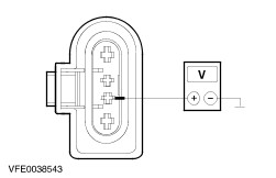
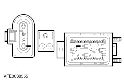
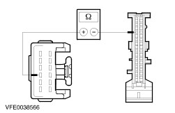
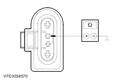
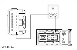
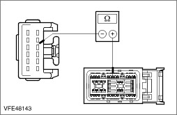
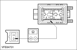
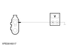
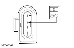
- Measure the resistance at the front windscreen wiper motor between pin 3 and pin 4 (or the housing of the wiper motor).
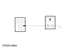
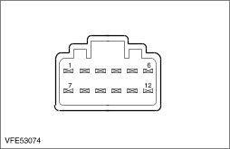
Wash/wipe system switch Pin assignment: | Circuit to test | Connect ohmmeter to the following terminal pins | Set the switch to the following position | The switch is OK if | | Intermittent | 3 and 12 | Intermittent | Circuit closed | | Variable delay | 3 and 7 | Intermittent level 1 | Circuit closed | | | 3 and 9 | Intermittent level 1 | Circuit open | | | 3 and 11 | Intermittent level 1 | Circuit open | | Variable delay | 3 and 7 | Intermittent level 2 | Circuit closed | | | 3 and 9 | Intermittent level 2 | Circuit closed | | | 3 and 11 | Intermittent level 2 | Circuit open | | Variable delay | 3 and 7 | Intermittent level 3 | Circuit open | | | 3 and 9 | Intermittent level 3 | Circuit closed | | | 3 and 11 | Intermittent level 3 | Circuit open | | Variable delay | 3 and 7 | Intermittent level 4 | Circuit open | | | 3 and 9 | Intermittent level 4 | Circuit closed | | | 3 and 11 | Intermittent level 4 | Circuit closed | | Variable delay | 3 and 7 | Intermittent level 5 | Circuit closed | | | 3 and 9 | Intermittent level 5 | Circuit closed | | | 3 and 11 | Intermittent level 5 | Circuit closed | | Variable delay | 3 and 7 | Intermittent level 6 | Circuit closed | | | 3 and 9 | Intermittent level 6 | Circuit open | | | 3 and 11 | Intermittent level 6 | Circuit closed | |