The RCM is located under the floor console, near to the gearshift lever. Installation marks on the module are to make sure it is aligned correctly.
Micromechanical sensors are incorporated into the RCM; this measures the vehicle's acceleration/deceleration in the event of a collision. The calculated value is evaluated by the RCM to determine the severity of the impact.
The RCM compares the values it receives from the crash sensor (if equipped), the side impact sensors and the internal micromechanical sensors. If the deceleration due to a frontal or side impact exceeds a stored value then the RCM triggers the air bag modules and safety belt pretensioners as required.
If the vehicle battery is destroyed in the collision, a voltage hold circuit in the RCM will still enable the air bag modules to be triggered up to 150 ms after the start of the impact.
If a system fault is detected by the RCM, the air bag warning lamp is illuminated. The fault can be located by carrying out a diagnostics check using the Worldwide Diagnostic System (WDS).
The RCM can be used again after a collision for up to 5 times, provided that the RCM is not physically damaged and that it passes a self-test.
The air bag modules are triggered by a direct current signal.
Crash Sensor - Vehicles built up to 05/2005
All vehicles, except vehicles with a convertible top, built 05/2005 onwards are not equipped with a crash sensor.
The crash sensor is installed at the front of the vehicle, behind the radiator grille. Data from the crash sensor is evaluated by the RCM to assess the severity of a frontal impact. The crash sensor transmits digitally encoded acceleration information to the RCM.
Power is supplied to the crash sensor by the RCM. If a crash sensor fails, the RCM stores a Diagnostic Trouble Code (DTC) .
Continued use of the crash sensor is permissible provided it has not been physically damaged and it passes a self-test.
The external shape of the crash sensor prevents it from being installed incorrectly.
Side Impact Sensors
The clockspring is designed to carry signals between the RCM and the driver air bag module. The clockspring is installed on the steering column, and consists of fixed and moving parts connected by a coiled Mylar tape with internal conducting tracks. The Mylar tape is able to 'wind up' and 'unwind' as the steering wheel is rotated, maintaining electrical contact at all times between the RCM and the driver air bag module.
Vehicles with stability assist have a steering wheel rotation sensor as an integral part of the clockspring.
Passenger Air Bag Deactivation
For vehicles with a convertible top, the PAD warning lamp is located in the overhead console.
After installing a PAD switch kit, the RCM must be re-configured using WDS.
Side Air Curtain Modules and Side Air Bag Modules
Side Air Curtains
The side air curtain modules are located in the roof rail between the A-pillar and C-pillar. They are attached to the upper part of the side panel and are hidden behind the vehicle trim panels.
The electrical connections for the 3-door are located at the base of the C-pillar, 4-door/ 5-door are located at the base of the D-pillar in the rear luggage compartment. The electrical connection for the Wagon is located in the roof in front of the liftgate.
In the event of a side impact the relevant side air curtain is deployed and forms a protective cushion between the corresponding side window and the head of the person(s) sat on the front and rear seat.
The side air curtains are deployed simultaneously with the side air bags.
Side Air Bags
The side air bags are incorporated in the front seat backrests; a sewn-on label on the respective backrest indicates the vehicle is equipped with side air bag modules.
When a side air bag is deployed, the seam of the seat cover tears open enabling the side air bag to inflate unhindered from the front seat backrest.
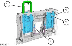
Roll Over Protection Unit - Convertible
2
-
Roll over protection unit
4
-
Roll over protection unit electrical connector
Sensors within the RCM monitor the vehicle for roll over in the event of a collision. If the roll over exceeds the stored value the RCM will trigger the roll over protection units.
When a signal is sent from the RCM to the rollover protection unit, the roll over bar lock is released, the roll over bar is deployed by spring pressure and is then locked in its fully extended position.
After a roll over protection unit is deployed the torsion wall and the roll over protection units are to be renewed.
Safety Belt Buckle and Pretensioners
The pyrotechnic pretensioners for the driver and front passenger safety belts are incorporated into the safety belt buckle stalks.
The driver's safety belt buckle has a switch for the safety belt monitoring facility, which is required by law in some markets.
The switch is connected to the RCM by means of a wiring harness.
In the event of a collision, the safety belt pretensioners can be deployed in one of two ways:
- On their own
- Simultaneously with the front air bag module(s)