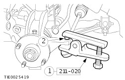
| Removal and Installation Special Tool(s) | | Alignment Pins, Subframe 205-316 (15-097A) | | | Separator, Ball Joint 211-020 (13-006) | General Equipment Removal | | -
NOTE:Make sure the road wheels are in the straight-ahead position. Centralize the steering and lock it in position. | | | -
Disconnect the steering column shaft from the steering gear pinion extension. | | | -
Remove the front wheels and tires.
For additional information, refer to: Wheel and Tire - 2.0L Duratec-RS (Zetec) (204-04 Wheels and Tires, Removal and Installation).
| | | -
CAUTION:Leave the tie-rod end retaining nuts in place to protect the ball joint studs. Loosen the tie-rod end retaining nuts. | | | -
CAUTION:Protect the ball joint seal using a soft cloth to prevent damage. Using the special tool, detach the tie-rod ends from the wheel knuckles. - Release the tie-rod ends.
- Remove and discard the tie-rod end retaining nuts.
| | | -
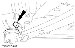
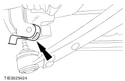
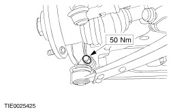
NOTE:Use a 5 mm Allen key to prevent the ball joint from rotating. Detach the stabilizer bar connecting links from the stabilizer bar. | | | -
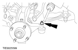
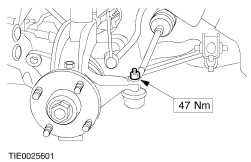
CAUTION:Protect the ball joint seal using a soft cloth to prevent damage. Detach the lower arm ball joints from the wheel knuckles. | | | -
Remove the engine rear support insulator to transaxle center bolt. | | | -
Remove the crossmember retaining bolts (support removed for clarity). | | | -
CAUTION:To prevent damage to the power steering lines, only lower the crossmember sufficently to allow the stabilizer bar to be removed. Lower the crossmember. | | | -
Remove the stabilizer bar. | | | -
Remove the stabilizer bar bushings. | Installation | | -
CAUTION:The stabilizer bar bushings must be located correctly on the flats of the stabilizer bar with no lubricant. Install the stabilizer bar bushings on both sides. | | | -
Set the stabilizer bar to the design height setting. - Locate the bushing against the spacer on both sides.
- Support the stabilizer bar to specification on both sides.
| | | -
Install the stabilizer bar clamps. - Apply water to the clamps to aid installation.
- Press the clamps onto the bushings.
| | | -
Install the stabilizer bar clamp rear retaining bolts. | | | -
NOTE:Do not fully tighten the stabilizer bar front retaining bolts at this stage. Install the stabilizer bar clamp front retaining bolts. | | | -
Tighten the stabilizer bar clamp retaining bolts on both sides. - Tighten the bolts in two stages:
- Stage 1: Tighten bolts 1 through 2 to 50 Nm.
- Stage 2: Tighten bolts 1 through 2 to 70 Nm.
| | | -
Remove the stabilizer bar supports. | | | -
CAUTION:Make sure the crossmember ball bearing washers are installed correctly. Using the special tool, align the crossmember. - Insert the alignment pins through the crossmember alignment holes and the washer.
- Slide the locking plates on top of the washer and into the groove of the tool and tighten the alignment pin sleeve.
- Raise the crossmember engaging the alignment pins into the chassis aligning holes.
| | | -
CAUTION:While tightening the crossmember retaining bolts, make sure the crossmember does not move. Install the crossmember retaining bolts. | | | -
Lower and remove the transmission jack. | | | -
Remove the subframe alignment pins. | | | -
Install the engine rear support insulator center bolt. | | | -
CAUTION:Make sure the heat shield is installed to prevent damage to the ball joint. Install the heat shield. | | | -
Attach the lower arm ball joint to the wheel knuckle. | | | -
Attach the stabilizer bar connecting links to the stabilizer bar. | | | -
WARNING:Install new tie-rod end retaining nuts. Failure to follow this instruction may result in personal injury. Attach the tie-rod ends to the wheel knuckles. | | | -
CAUTION:Make sure the wheel hubs are in the straight-ahead position, before lowering the vehicle. Install the front wheels and tires.
For additional information, refer to: Wheel and Tire - 2.0L Duratec-RS (Zetec) (204-04 Wheels and Tires, Removal and Installation).
| | | -
WARNING:Install a new pinch bolt. Failure to follow this instruction may result in personal injury. Connect the steering column shaft to the steering gear pinion extension. | | |