| Removal and Installation Special Tool(s) | | Lever, Wheel Knuckle 204-159 (14-039) | | | Separator, Ball Joint 211-020 (13-006) | Removal | | -
Detach the brake hose from the suspension strut. | | | -
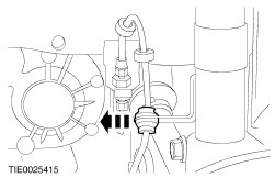
NOTE:Use a 5 mm allen key to prevent the ball joint from rotating. Detach the stabilizer bar connecting link from the suspension strut. | | | -
CAUTION:Suspend the brake caliper to prevent load being placed on the brake hose. Detach the front brake caliper from the wheel knuckle. | | | -
CAUTION:Leave the tie-rod end retaining nut in place to protect the ball joint stud. Loosen the tie-rod end retaining nut. | | | -
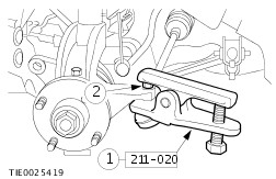
CAUTION:Protect the ball joint seal using a soft cloth to prevent damage. Using the special tool, detach the tie-rod end from the wheel knuckle. - Release the tie-rod end.
- Remove and discard the tie-rod end retaining nut.
| | | -
CAUTION:Protect the ball joint seal using a soft cloth to prevent damage. Detach the lower arm ball joint from the wheel knuckle. | | | -
Remove the wheel knuckle to suspension strut pinch bolt. | | | -
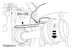
CAUTION:Support the halfshaft. The inner joint must not be bent more than 18 degrees. The outer joint must not be bent more than 45 degrees. Using the special tool, detach the wheel knuckle from the suspension strut. - Insert the special tool and rotate through 90 degrees.
- Remove the wheel knuckle.
| | | -
CAUTION:With the aid of another technician, support the strut and spring assembly. Remove the strut and spring assembly. | Installation WARNING:Install a new tie-rod end retaining nut. Failure to follow this instruction may result in personal injury. CAUTION:Make sure the heat shield is installed to prevent damage to the ball joint. CAUTION:The lower arm pinch bolt must be installed from the rear of the wheel knuckle. | | -
To install, reverse the removal procedure. | | |