| PINPOINT TEST D : AIR CONDITIONING INOPERATIVE (HEATER BLOWER FUNCTION OK) |
| TEST CONDITIONS | DETAILS/RESULTS/ACTIONS |
| D1: CHECK FUSE F15 |
| | 1 Ignition switch in position 0. |
| | 2 CHECK fuse F15 (BJB). |
| | Is the fuse OK? Yes No RENEW fuse F15 (10 A). If the fuse blows again after switching on the air conditioning, CHECK the A/C compressor clutch diode and RENEW as necessary. If the diode is OK, LOCATE and REPAIR the short to ground using the Wiring Diagrams. CHECK the operation of the system. |
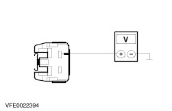
| D2: CHECK THE VOLTAGE AT FUSE F15 |
| | 1 Connect fuse F15 (BJB). |
| | 2 Measure the voltage between fuse F15 (10 A) and ground. |
| | Does the meter display battery voltage? Yes No REPAIR the voltage supply to fuse F15 using the Wiring Diagrams. CHECK the operation of the system. |
| D3: CHECK FUSE F36 |
| | 1 CHECK fuse F36 (CJB). |
| | Is the fuse OK? Yes No RENEW fuse F36 (7.5 A). If the fuse blows again, LOCATE and REPAIR the short to ground using the Wiring Diagrams. CHECK the operation of the system. |
| D4: CHECK THE VOLTAGE AT FUSE F36 |
| | 1 Connect fuse F36 (CJB). |
| | 2 Measure the voltage between fuse F36 (7.5 A) and ground. |
| | Does the meter display battery voltage? Yes No REPAIR the voltage supply to fuse F36 using the Wiring Diagrams. CHECK the operation of the system. |
| D5: CHECK FUSE F45 |
| | 1 CHECK fuse F45 (CJB). |
| | Is the fuse OK? Yes No RENEW fuse F45 (7.5 A). If the fuse blows again, LOCATE and REPAIR the short to ground using the Wiring Diagrams. CHECK the operation of the system. |
| D6: CHECK THE VOLTAGE AT FUSE F45 |
| | 1 Connect fuse F45 (CJB). |
| | 2 Ignition switch in position II. |
| | 3 Measure the voltage between fuse F45 (7.5 A) and ground. |
| | Does the meter display battery voltage? Yes No REPAIR the voltage supply to fuse F45 using the Wiring Diagrams. CHECK the operation of the system. |
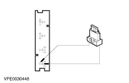
| D7: CHECK THE VOLTAGE SUPPLY AT THE A/C SYSTEM WIDE OPEN THROTTLE RELAY (WOT) |
| | 1 Ignition switch in position 0. |
| | 2 Disconnect A/C WOT relay C1011 (BJB). |
| | 3 Measure the voltage between the A/C WOT relay, socket C1011, pin 3, circuit 15-FA38 (GN/RD), wiring harness side and ground. |
| | Does the meter display battery voltage? Yes No LOCATE and REPAIR the break in circuit 15-FA38 (GN/RD) between fuse F15 and the A/C WOT relay using the Wiring Diagrams. CHECK the operation of the system. |
| D8: CHECK THE CONTROL VOLTAGE AT THE A/C WOT RELAY |
| | 1 Ignition switch in position III. |
| | 2 Measure the voltage between the A/C WOT relay, socket C1011, pin 1, circuit 15-FA11 (GN/YE), wiring harness side and ground. |
| | Does the meter display battery voltage? Yes No LOCATE and REPAIR the break in circuit 15-FA11 (GN/YE) between soldered connection S117 and the A/C WOT relay using the Wiring Diagrams. CHECK the operation of the system. |
| D9: CHECK THE A/C COMPRESSOR CLUTCH CIRCUIT |
| | 1 Ignition switch in position 0. |
| | 2 Use a fused test cable (10 A) to bridge the A/C WOT relay, socket C1011, pins 3 and pin 5, wiring harness side. |
| | 3 Ignition switch in position III. |
| | 4 Check the operation of the A/C compressor clutch. |
| | Is the A/C compressor operative? Yes No |
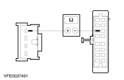
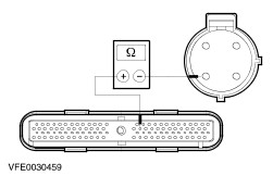
| D10: CHECK FOR OPEN CIRCUIT BETWEEN THE A/C WOT RELAY AND THE A/C COMPRESSOR CLUTCH |
| | 1 Ignition switch in position 0. |
| | 2 Disconnect connector C952 from A/C compressor clutch. |
| | 3 Measure the resistance between the A/C WOT relay, socket C1011, pin 5, wiring harness side and the A/C compressor clutch, connector C952, pin 1, circuit 15S-FA6 (GN/YE), wiring harness side. |
| | Is a resistance of less than 2 Ohms registered? Yes No LOCATE and REPAIR the open circuit between the A/C WOT relay and the A/C compressor clutch using the Wiring Diagrams. CHECK the operation of the system. |
| D11: CHECK THE GROUND CONNECTION OF THE A/C COMPRESSOR CLUTCH |
| | 1 Measure the resistance between the A/C compressor clutch, connector C952, pin 2, circuit 31-FA6 (BK), wiring harness side and ground. |
| | Is a resistance of less than 2 Ohms registered? Yes RENEW the A/C compressor clutch. CHECK the operation of the system. No LOCATE and REPAIR the break in the circuit between the A/C compressor clutch and ground connection G56 using the Wiring Diagrams. CHECK the operation of the system. |
| D12: CHECK THE GROUND CONNECTION OF THE A/C WOT RELAY |
| | 1 Switch on the heater blower. |
| | 2 Switch on the air-conditioning system. |
| | CAUTION:It is imperative that a test lamp with a nominal voltage of 12 V and a nominal power rating of 1.2 W is used during the following test. Otherwise the PCM could be damaged, or the test results could be incorrect. 3 Use a test lamp (12 V, 1.2 W) to check the voltage at the A/C WOT relay, socket C1011, between pin 1 and pin 2, wiring harness side. |
| | Does the test lamp illuminate? Yes RENEW the A/C WOT relay. CHECK the operation of the system. No |
| D13: CHECK THE REFRIGERANT QUANTITY |
| | 1 Ignition switch in position 0. |
| | 2 |
| | Is the refrigerant quantity in accordance with manufacturer's specifications? Yes No FILL the system with the correct quantity of refrigerant. CHECK the system for leaks and CHECK the operation of the system. |
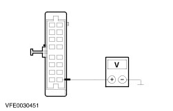
| D14: CHECK THE CIRCUIT BETWEEN THE HEATER CONTROL MODULE AND THE PCM FOR SHORT TO VOLTAGE SUPPLY |
| | 1 Disconnect connector C380 from heater control module. |
| | 2 Disconnect connector C415 from PCM. |
| | 3 Ignition switch in position II. |
| | 4 Measure the voltage between the heater control module, connector C380, pin 9, circuit 15S-FA38 (GN/RD), wiring harness side and ground. |
| | Is a voltage measured? Yes LOCATE and REPAIR the short to voltage supply in the circuit between the heater control module and the PCM using the Wiring Diagrams. CHECK the operation of the system. No |
| D15: CHECK THE CIRCUIT BETWEEN THE HEATER CONTROL MODULE AND THE PCM FOR SHORT TO GROUND |
| | 1 Ignition switch in position 0. |
| | 2 Measure the resistance between the heater control module, connector C380, pin 9, circuit 15S-FA38 (GN/RD), wiring harness side and ground. |
| | Is a resistance of less than 10,000 Ohms registered? Yes LOCATE and REPAIR the short to ground in the circuit between the heater control module and the PCM using the Wiring Diagrams. CHECK the operation of the system. No |
| D16: CHECK THE VOLTAGE AT THE DUAL PRESSURE SWITCH |
| | 1 Connect connector C380 to heater control module. |
| | 2 Connect connector C415 to PCM. |
| | 3 Disconnect connector C882 from dual pressure switch. |
| | 4 Ignition switch in position III. |
| | 5 Switch on the heater blower. |
| | 6 Switch on the air-conditioning system. |
| | 7 Measure the voltage between the dual pressure switch, connector C882, pin 1, circuit 15S-FA38 (GN/RD), wiring harness side and ground. |
| | Does the meter display battery voltage? Yes No |
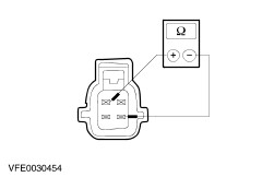
| D17: CHECK THE DUAL PRESSURE SWITCH |
| | 1 Ignition switch in position 0. |
| | 2 Measure the resistance at the dual pressure switch, connector C882, between pin 1 and pin 4, component side. |
| | Is a resistance of less than 2 Ohms registered? Yes No RENEW the dual pressure switch. CHECK the operation of the system. |
| D18: CHECK THE VOLTAGE AT THE A/C COMPRESSOR SWITCH |
| | 1 Connect connector C882 to dual pressure switch. |
| | 2 Disconnect connector C692 from A/C compressor switch. |
| | 3 Ignition switch in position III. |
| | 4 Switch on the heater blower. |
| | 5 Switch on the air-conditioning system. |
| | 6 Measure the voltage between the A/C compressor switch, connector C692, pin 1, circuit 15-FA17 (GN/OG), wiring harness side and ground. |
| | Does the meter display battery voltage? Yes No LOCATE and REPAIR the break in circuit 15S-FA17 (GN/OG) between the dual pressure switch and the A/C compressor switch using the Wiring Diagrams. CHECK the operation of the system. |
| D19: CHECK THE A/C COMPRESSOR SWITCH |
| | 1 Ignition switch in position 0. |
| | 2 Measure the resistance at the A/C compressor switch, connector C692, between pin 1 and pin 4, component side. |
| | Is a resistance of less than 2 Ohms registered? Yes No RENEW the A/C compressor switch. CHECK the operation of the system. |
| D20: CHECK FOR OPEN CIRCUIT BETWEEN THE A/C COMPRESSOR SWITCH AND THE POWER TRAIN CONTROL MODULE (PCM) |
| | 1 Disconnect connector C415 from PCM. |
| | 2 Measure the resistance between PCM, connector C415, pin 41, circuit 15S-RE8 (GN/YE), wiring harness side and A/C compressor switch, connector C692, pin 4, circuit 15S-RE8 (GN/YE), wiring harness side. |
| | Is a resistance of less than 2 Ohms registered? Yes No LOCATE and REPAIR the break in circuit 15S-RE8 (GN/YE) between the A/C compressor switch and the PCM using the Wiring Diagrams. CHECK the operation of the system. |
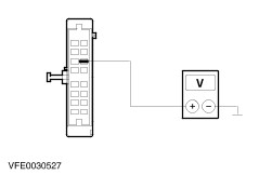
| D21: CHECK THE CIRCUIT BETWEEN THE A/C WOT RELAY AND THE PCM FOR SHORT TO VOLTAGE SUPPLY |
| | 1 Ignition switch in position II. |
| | 2 Measure the voltage between the PCM, connector C415, pin 69, circuit 31S-FA11 (BK/YE), wiring harness side and ground. |
| | Is a voltage measured? Yes LOCATE and REPAIR the short to voltage supply in circuit 31S-FA11 (BK/YE) between the A/C WOT relay and the PCM using the Wiring Diagrams. CHECK the operation of the system. No |
| D22: CHECK THE CIRCUIT BETWEEN THE A/C WOT RELAY AND THE PCM FOR SHORT TO GROUND |
| | 1 Ignition switch in position 0. |
| | 2 Measure the voltage between the PCM, connector C415, pin 69, circuit 31S-FA11 (BK/YE), wiring harness side and ground. |
| | Is a resistance of less than 10,000 Ohms registered? Yes LOCATE and REPAIR the short to ground in circuit 31S-FA11 (BK/YE) between the A/C WOT relay and the PCM using the Wiring Diagrams. CHECK the operation of the system. No |
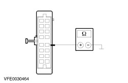
| D23: CHECK FOR OPEN CIRCUIT BETWEEN THE A/C WOT RELAY AND THE PCM |
| | 1 Measure the resistance between the PCM, connector C415, pin 69, circuit 31S-FA11 (BK/YE), wiring harness side and the A/C WOT relay, socket C1011, pin 2, wiring harness side. |
| | Is a resistance of less than 2 Ohms registered? Yes CHECK the PCM and RENEW if necessary. CHECK the operation of the system. No LOCATE and REPAIR the break in the circuit between the PCM and the A/C WOT relay using the Wiring Diagrams. CHECK the operation of the system. |
| D24: CHECK FOR OPEN CIRCUIT BETWEEN THE DUAL PRESSURE SWITCH AND THE HEATER CONTROL MODULE |
| | 1 Ignition switch in position 0. |
| | 2 Disconnect connector C380 from heater control module. |
| | 3 Measure the resistance between the dual pressure switch, connector C882, pin 1, circuit 15S-FA38 (GN/RD), wiring harness side and the heater control module, connector C380, pin 9, circuit 15S-FA38 (GN/RD), wiring harness side. |
| | Is a resistance of less than 2 Ohms registered? Yes No LOCATE and REPAIR the break in circuit in 15S-FA38 (GN/RD) between the dual pressure switch and the heater control module using the Wiring Diagrams. CHECK the operation of the system. |
| D25: CHECK THE GROUND CONNECTION OF THE HEATER CONTROL MODULE |
| | 1 Measure the resistance between the heater control module, connector C380, pin 12, circuit 91-FA13 (BK/OG), wiring harness side and ground. |
| | Is a resistance of less than 2 Ohms registered? Yes No LOCATE and REPAIR the break in the circuit between the heater control module and ground connection G41 using the Wiring Diagrams. CHECK the operation of the system. |
| D26: CHECK THE VOLTAGE AT THE HEATER CONTROL MODULE |
| | 1 Measure the voltage between the heater control module, connector C380, pin 8, circuit 29-FA13 (OG), wiring harness side and ground. |
| | Does the meter display battery voltage? Yes No LOCATE and REPAIR the break in the circuit between the heater control module and fuse F36 using the Wiring Diagrams. CHECK the operation of the system. |
| D27: CHECK THE VOLTAGE AT THE HEATER CONTROL MODULE |
| | 1 Ignition switch in position II. |
| | 2 Measure the voltage between the heater control module, connector C380, pin 10, circuit 15-FA13 (GN/RD), wiring harness side and ground. |
| | Does the meter display battery voltage? Yes No LOCATE and REPAIR the break in the circuit between the heater control module and fuse F45 using the Wiring Diagrams. CHECK the operation of the system. |
| D28: CHECK THE CONTROL VOLTAGE AT THE HEATER CONTROL MODULE |
| | 1 Set the heater blower switch to "Off". |
| | 2 Measure the voltage between the heater control module, connector C380, pin 6, circuit 31S-FA26 (BK/RD), wiring harness side and ground. |
| | Does the meter display battery voltage? Yes No LOCATE and REPAIR the break in circuit 31S-FA26 (BK/RD) between the heater control module and the heater blower switch using the Wiring Diagrams. CHECK the operation of the system. |
| D29: CHECK THE VOLTAGE AT THE HEATER CONTROL MODULE |
| | 1 Ignition switch in position III. |
| | 2 Measure the voltage between the heater control module, connector C380, pin 11, circuit 64-HB6A (BU), wiring harness side and ground. |
| | Does the meter display battery voltage? Yes CHECK the heater control module and RENEW as necessary. CHECK the operation of the system. No LOCATE and REPAIR the break in the circuit between the heater control module and the engine run relay using the Wiring Diagrams. CHECK the operation of the system. |