| PINPOINT TEST D : THE DEFROST SYSTEM IS INOPERATIVE |
| TEST CONDITIONS | DETAILS/RESULTS/ACTIONS |
| D1: CHECK THE OPERATION OF THE HEATED REAR WINDOW CIRCUIT |
| | 1 Ignition switch in position II. |
| | 2 Operate the heated rear window control switch. |
| | Does the heated rear window circuit function correctly? Yes No |
| D2: CHECK THE OPERATION OF THE HEATED WINDSHIELD CIRCUIT |
| | 1 Ignition switch in position III. |
| | 2 Ignition switch in position II. |
| | 3 With the engine running, operate the heated windshield control switch. |
| | Does the heated windshield circuit function correctly? Yes VERIFY the customer concern. No |
| D3: CHECK THE OPERATION OF THE HEATED EXTERIOR MIRRORS |
| | 1 Operate the heated rear window control switch. |
| | Do the exterior heated mirrors function correctly? Yes No |
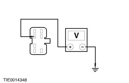
| D4: CHECK FOR VOLTAGE TO THE HEATED REAR WINDOW |
| | 1 Ignition switch in position 0. |
| | 2 Disconnect Heated Rear Window C949. |
| | 3 Ignition switch in position II. |
| | 4 Measure the voltage between the heated rear window C949 pin 1, circuit 15S-HB19 (GN/BU), harness side and ground. |
| | Is the voltage greater than 10 volts? Yes No REPAIR circuit 15S-HB19 (GN/BU). TEST the system for normal operation. |
| D5: CHECK THE HEATED REAR WINDOW GROUND CIRCUIT |
| | 1 Ignition switch in position 0. |
| | 2 Measure the resistance between the heated rear window ground circuit and ground. |
| | Is the resistance less than 5 ohms? Yes INSTALL a new heated rear window. TEST the system for normal operation. No REPAIR the heated rear window ground circuit. TEST the system for normal operation. |
| D6: CHECK THE OPERATION OF THE HEATED WINDSHIELD RELAY |
| | 1 Operate the heated windshield control switch. |
| | Did the relay click? Yes No |
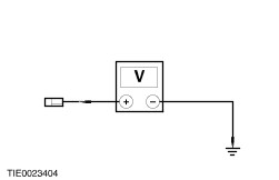
| D7: CHECK FOR VOLTAGE TO THE HEATED WINDSHIELD GRID WIRES |
| | 1 Ignition switch in position 0. |
| | 2 Disconnect Heated Windshield C634 or C635.. |
| | 3 Ignition switch in position III. |
| | 4 Ignition switch in position II. |
| | 5 Measure the voltage between the: - Heated windshield left-hand grid wire C634 pin 1, circuit 64S-HB12 (BU), harness side and ground.
- Heated windshield right-hand grid wire C635 pin 1, circuit 64S-HB25 (BU/RD), harness side and ground.
|
| | Are the voltages greater than 10 volts? Yes No |
| D8: CHECK THE HEATED WINDSHIELD GRID WIRE GROUND CIRCUITS |
| | 1 Ignition switch in position 0. |
| | 2 Measure the resistance between the heated windshield ground circuits and ground. |
| | Are the resistances less than 5 ohms? Yes No REPAIR the heated windshield ground circuit. TEST the system for normal operation. |
| D9: CHECK THE HEATED WINDSHIELD GRID WIRES |
| | 1 Measure the resistance between the: - Heated windshield grid wire C634 pin 1 (LH element), component side and ground.
- Heated windshield grid wire C635 pin 1 (RH element), component side and ground.
|
| | Is the resistance greater than 10,000 ohms? Yes INSTALL a new windshield. TEST the system for normal operation. No VERIFY the customer concern. |
| D10: CHECK THE OPERATION OF THE HEATED REAR WINDOW RELAY |
| | 1 Operate the heated rear window control switch. |
| | Does the heated rear window relay click? Yes No |
| D11: CHECK FOR VOLTAGE TO THE CENTRAL JUNCTION BOX (CJB) FUSE 49 (25A) |
| | 1 Ignition switch in position 0. |
| | 2 Disconnect Fuse 49 (25A). |
| | 3 Measure the voltage between fuse 49 (25A) input and ground. |
| | Is the voltage greater than 10 volts? Yes No REPAIR the central junction box. TEST the system for normal operation. |
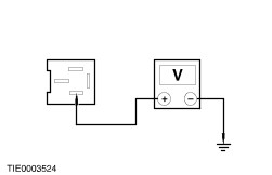
| D12: CHECK FOR VOLTAGE TO THE HEATED REAR WINDOW |
| | 1 Disconnect Heated Rear Window C949. |
| | 2 Ignition switch in position II. |
| | 3 Measure the voltage between the heated rear window C949 pin 1, circuit 15S-HB19 (GN/BU), harness side and ground. |
| | Is the voltage greater than 10 volts? Yes No REPAIR circuit 15S-HB19 (GN/BU). TEST the system for normal operation. |
| D13: CHECK THE HEATED REAR WINDOW GROUND CIRCUIT |
| | 1 Ignition switch in position 0. |
| | 2 Measure the resistance between the heated rear window ground circuit and ground. |
| | Is the resistance less than 5 ohms? Yes INSTALL a new heated rear window. TEST the system for normal operation. No REPAIR the heated rear window ground circuit. TEST the system for normal operation. |
| D14: CHECK VOLTAGE TO THE HEATED WINDSHIELD RELAY |
| | 1 Ignition switch in position 0. |
| | 2 Disconnect Heated Windshield Relay C1003. |
| | 3 Ignition switch in position III. |
| | 4 Ignition switch in position II. |
| | 5 Measure the voltage between the heated windshield relay C1003 pin 1, circuit 64-HB7 (BU/RD), harness side and ground. |
| | Is the voltage greater than 10 volts? Yes No REPAIR circuit 64-HB7 (BU/RD). TEST the system for normal operation. |
| D15: CHECK FOR CONTINUITY BETWEEN THE CENTRAL TIMER MODULE (CTM) AND GROUND |
| | 1 Ignition switch in position 0. |
| | 2 Disconnect CTM C1000. |
| | 3 Operate the heated windshield control switch. |
| | 4 Measure the resistance between the CTM C1000 pin 10, circuit 31S-HB9 (BK/WH), harness side and ground. |
| | Is the resistance less than 5 ohms? Yes No |
| D16: CHECK FOR CONTINUITY BETWEEN THE HEATED WINDSHIELD RELAY AND THE CTM |
| | 1 Measure the resistance between the heated windshield relay C1003 pin 2, circuit 31S-HB7 (BK/BU), harness side and the central timer module C1000 pin 32 (CJB), harness side. |
| | Is the resistance less than 5 ohms? Yes INSTALL a new heated windshield relay. TEST the system for normal operation. No REPAIR circuit 31S-HB7 (BK/BU). TEST the system for normal operation. |
| D17: CHECK FOR CONTINUITY BETWEEN THE HEATED WINDSHIELD RELAY AND THE HEATED WINDSHIELD GRID WIRES |
| | 1 Ignition switch in position 0. |
| | 2 Disconnect Heated Windshield Relay C1003. |
| | 3 Measure the resistance between the: - Left-hand grid wire heated windshield relay C1003 pin 5, circuit 64S-HB1 (BU/RD), harness side and the heated windshield left-hand grid wire C634 pin 1, circuit 64S-HB12 (BU), harness side.
- Right-hand grid wire heated windshield relay C1003 pin 5, circuit 64S-HB1 (BU/RD), harness side and the heated windshield right-hand grid wire C635 pin 1, circuit 64S-HB25 (BU/RD), harness side.
|
| | Are the resistances less than 5 ohms? Yes INSTALL a new heated windshield relay. TEST the system for normal operation. No REPAIR circuit 64S-HB1 (BU/RD), circuit 64S-HB12 (BU) or circuit 64S-HB25 (BU/RD). TEST the system for normal operation. |
| D18: CHECK FOR CONTINUITY BETWEEN THE HEATED REAR WINDOW RELAY AND THE CENTRAL TIMER MODULE (CTM) |
| | 1 Ignition switch in position 0. |
| | 2 Disconnect Heated Rear Window Relay C1025. |
| | 3 Disconnect GEM C105. |
| | 4 Measure the resistance between the heated rear window relay C1025 pin 2 (CJB), harness side and the central timer module C1000 pin 4 (CJB), harness side. |
| | Is the resistance less than 5 ohms? Yes No REPAIR the central junction box. TEST the system for normal operation. |
| D19: CHECK FOR CONTINUITY BETWEEN THE CTM AND GROUND |
| | 1 Operate the heated rear window control switch. |
| | 2 Measure the resistance between the central timer module C1000 pin 19 (CJB), harness side and ground. |
| | Is the resistance less than 5 ohms? Yes INSTALL a new heated rear window relay. TEST the system for normal operation. No |
| D20: CHECK FOR CONTINUITY BETWEEN THE CENTRAL TIMER MODULE AND THE HEATER CONTROL MODULE |
| | 1 Ignition switch in position 0. |
| | 2 Disconnect Heater Control Module C380. |
| | 3 Measure the resistance between the central timer module C1000 pin 10 (CJB), harness side and the heater control module C380 pin 5, circuit 31S-HB9 (BK/WH), harness side. |
| | Is the resistance less than 5 ohms? Yes No REPAIR circuit 31S-HB9 (BK/WH). TEST the system for normal operation. |
| D21: CHECK THE HEATER CONTROL MODULE GROUND CIRCUIT |
| | 1 Measure the resistance between the heater control module C380 pin 12, circuit 91-FA13 (BK/OG) harness side and ground. |
| | Is the resistance less than 5 ohms? Yes INSTALL a new heater control module. TEST the system for normal operation. No REPAIR circuit 91-FA13 (BK/OG). TEST the system for normal operation. |
| D22: CHECK FOR CONTINUITY BETWEEN THE CTM AND THE HEATER CONTROL MODULE |
| | 1 Disconnect Heater Control Module C380. |
| | 2 Measure the resistance between the central timer module C1000 pin 19 (CJB), harness side and the heater control module C380 pin 3, circuit 31S-HB1 (BK/BU), harness side. |
| | Is the resistance less than 5 ohms? Yes No REPAIR circuit 31S-HB22 (BK/GN). TEST the system for normal operation. |
| D23: CHECK FOR THE CONTINUITY BETWEEN THE HEATER CONTROL MODULE AND GROUND |
| | 1 Measure the resistance between the heater control module C380 pin 12, circuit 91-FA13 (BK/OG), harness side and ground. |
| | Is the resistance less than 5 ohms? Yes INSTALL a new heater control module. TEST the system for normal operation. No REPAIR circuit 91-FA13 (BK/OG). TEST the system for normal operation. |