| Diagnosis and Testing Pinpoint Tests | PINPOINT TEST A : NO COMMUNICATION WITH THE MODULE | | TEST CONDITIONS | DETAILS/RESULTS/ACTIONS | | A1: CHECK THAT WDS/FDS 2000 IS COMMUNICATING THROUGH THE DATA LINK CONNECTOR (DLC) | | | 1 Select an alternative system to check the DLC. | | | Is WDS/FDS 2000 able to communicate with the selected system? Yes No CHECK the DLC. For additional information, refer to the Wiring Diagrams. | | A2: CHECK THE AIR BAG WARNING INDICATOR | | | 1 Ignition switch in position II. | | | 2 The air bag warning indicator should illuminate when the ignition is in the ON position for three seconds then go out. If a fault is present, the air bag warning will begin to flash after five seconds. | | | Is the air bag warning indicator operating? Yes No CHECK the instrument cluster. For additional information, refer to the Wiring Diagrams. | | A3: CHECK THE DLC CIRCUIT | WARNING:Wait at least one minute after disconnecting the battery ground cable before disconnecting any supplemental restraint system electrical connector. Failure to follow this instruction may result in personal injury. | | | 1 Ignition switch in position 0. | | | 2 | | | 3 Disconnect Air Bag Control Module C424. | | | 4 Measure the resistance between the DLC C200 pin 7, circuit 8-EE18 (WH/BK) and the air bag control module C424 pin 7, circuit 8-EE7 (WH/RD). | | | Is the resistance less than 5 ohms? Yes No | | PINPOINT TEST B : DTC B1921: AIR BAG WARNING INDICATOR GROUND MONITORING CIRCUIT OPEN | | TEST CONDITIONS | DETAILS/RESULTS/ACTIONS | | B1: CHECK THE AIR BAG CONTROL MODULE MOUNTING | WARNING:Wait at least one minute after disconnecting the battery ground cable before disconnecting any supplemental restraint system electrical connector. Failure to follow this instruction may result in personal injury. | | | 1 | | | 2 | | | 3 Check the security of the air bag control module. | | | Is the air bag control module correctly mounted and all bolts tightened to the correct torque? Yes No | | B2: CHECK THE AIR BAG CONTROL MODULE CASE GROUND | | | 1 Disconnect Air Bag Control Module C424. | | | 2 Measure the resistance between the air bag control module C424 pin 9, circuit 91-JA10 (BK/RD), harness side and the air bag control module housing. | | | Is the resistance less than 5 ohms? Yes No | | PINPOINT TEST C : DTC B1318: BATTERY VOLTAGE LOW | | TEST CONDITIONS | DETAILS/RESULTS/ACTIONS | | C1: CHECK THE BATTERY VOLTAGE | | | 1 Ignition switch in position II. | | | 2 Check the battery voltage with the ignition in the ON position. | | | Is the battery voltage greater than 9 volts? Yes No | | C2: CHECK THE CONDITION OF THE FUSE. | | | 1 Ignition switch in position 0. | | | 2 Disconnect Fuse 60 (7.5A). | | | 3 CHECK Fuse 60 (7.5A). | | | 4 Check the condition of fuse 60 (7.5A). | | | Is any corrosion present on the fuse or the terminals? Yes CLEAN the terminals. INSTALL a new fuse 60 (7.5A). REPEAT the self-test, CLEAR the DTCs. No | | C3: CHECK THE AIR BAG CONTROL MODULE SUPPLY CIRCUIT | WARNING:Wait at least one minute after disconnecting the battery ground cable before disconnecting any supplemental restraint system electrical connector. Failure to follow this instruction may result in personal injury. | | | 1 | | | 2 Disconnect Air Bag Control Module C424. | | | 3 Measure the resistance between the output side of fuse 60 (7.5A) and the air bag control module C424 pin 8, circuit 15-JA10 (GN/OG) harness side. | | | Is the resistance less than 5 ohms? Yes No | | C4: CHECK THE AIR BAG CONTROL MODULE GROUND CIRCUIT | | | 1 Measure the resistance between the air bag control module C424 pin 9, circuit 91-JA10 (BK/RD) and the A-pillar ground G41. | | | Is the resistance less than 2 ohms? Yes No | | PINPOINT TEST D : DTC B1869: AIR BAG WARNING INDICATOR OPEN CIRCUIT OR SHORT TO GROUND | | TEST CONDITIONS | DETAILS/RESULTS/ACTIONS | | D1: CHECK THE AIR BAG WARNING INDICATOR | | | 1 Ignition switch in position II. | | | 2 Check the air bag warning indicator. | | | Is the air bag warning indicator illuminated continuously? Yes No | | D2: CHECK THE AIR BAG WARNING INDICATOR CIRCUIT | WARNING:Wait at least one minute after disconnecting the battery ground cable before disconnecting any supplemental restraint system electrical connector. Failure to follow this instruction may result in personal injury. | | | 1 Ignition switch in position 0. | | | 2 | | | 3 Disconnect Air Bag Control Module C424. | | | 4 Disconnect Instrument Cluster C809. | | | 5 Measure the resistance between the instrument cluster C809 pin 22, circuit 91S-JA14 (BK/GN) and the air bag control module C424 pin 4, circuit 91S-JA14 (BK/GN) harness side. | | | Is the resistance less than 5 ohms? Yes No | | D3: CHECK THE AIR BAG WARNING INDICATOR FUNCTION | | | 1 Connect Instrument Cluster C809. | | | 2 Install a fused (7.5A) jumper wire between the air bag control module C424 pin 4, circuit 91S-JA14 (BK/GN) harness side and ground. | | | 3 TURN the ignition ON. | | | Is the air bag warning indicator illuminated? Yes No | | D4: CHECK THE AIR BAG WARNING INDICATOR FUNCTION (CONT.) | | | 1 With the fused (7.5A) jumper wire between the air bag control module C424 pin 4, circuit 91S-JA14 (BK/GN) and ground. | | | 2 Disconnect the fused jumper wire from the ground. | | | Is the air bag warning indicator illuminated? Yes No | | D5: CHECK THE INSTRUMENT CLUSTER WARNING INDICATORS | WARNING:Wait at least one minute after disconnecting the battery ground cable before disconnecting any supplemental restraint system electrical connector. Failure to follow this instruction may result in personal injury. | NOTE:The air bag control module will only activate the audible warning if there is an air bag warning indicator fault AND another fault in the supplemental restraint system, (for example an open circuit on the driver air bag module) in all cases REPAIR the air bag warning indicator first. | | | 1 Ignition switch in position 0. | | | 2 | | | 3 Ignition switch in position II. | | | 4 Check the instrument cluster warning indicators. | | | Are the warning indicators illuminated when the ignition is switched to the ON position? Yes No CHECK the instrument cluster fuse. For additional information refer to the Wiring Diagrams. | | D6: CHECK THE AIR BAG WARNING INDICATOR CIRCUIT | | | 1 Ignition switch in position 0. | | | 2 Disconnect Air Bag Control Module C424. | | | 3 Measure the resistance between the air bag control module C424 pin 4, circuit 91S-JA14 (BK/GN) harness side and ground. | | | Is the resistance greater than 10,000 ohms? Yes No | | PINPOINT TEST E : DTC B1870: AIR BAG WARNING INDICATOR SHORT TO BATTERY | WARNING:Wait at least one minute after disconnecting the battery ground cable before disconnecting any supplemental restraint system electrical connector. Failure to follow this instruction may result in personal injury. | | TEST CONDITIONS | DETAILS/RESULTS/ACTIONS | | E1: CHECK THE AIRBAG WARNING INDICATOR CIRCUIT | | | 1 | | | 2 Disconnect Air Bag Control Module C424. | | | 3 Disconnect Instrument Cluster C809. | | | 4 Ignition switch in position II. | | | 5 Measure the voltage between the air bag control module C424 pin 4, circuit 91S-JA14 (BK/GN) harness side and ground. | | | Is any voltage present? Yes No | | PINPOINT TEST F : DTC B1887: DRIVER AIR BAG SHORT TO GROUND | WARNING:Wait at least one minute after disconnecting the battery ground cable before disconnecting any supplemental restraint system electrical connectors. Failure to follow this instruction may result in personal injury. | | TEST CONDITIONS | DETAILS/RESULTS/ACTIONS | | F1: CHECK THE DRIVER AIR BAG CIRCUIT | | | 1 | | | 2 Ignition switch in position II. | | | 3 Carry out the self-test with the simulators installed. | | | Does the system prove out correctly? Yes No | | F2: CHECK THE DRIVER AIR BAG MODULE | WARNING:Do not proceed with this test unless using WDS/FDS 2000. Failure to follow this instruction may result in personal injury. | | | 1 Connect the Test and Deployment lead 40-007-01 to the driver air bag module. | | | 2 Select DMM specific on WDS/FDS 2000. | | | 3 Connect the Test and Deployment lead to WDS/FDS 2000. | | | 4 Measure the resistance between each of the terminals and the air bag module case. | | | Is the resistance greater than 10,000 ohms? Yes No | | F3: CHECK THE AIR BAG WIRING SUB-HARNESS FOR A SHORT TO GROUND | | | 1 Ignition switch in position 0. | | | 2 Disconnect Air Bag Control Module C424. | | | 3 Disconnect Driver Air Bag Module Simulator. | | | 4 Measure the resistance between: - the air bag control module C424 pin 2, circuit 15S-JA8 (GN/RD) and pin 9, circuit 91-JA10 (BK/RD) harness side; and
- the air bag control module C424 pin 2, circuit 15S-JA8 (GN/RD) harness side and ground; and
- the air bag control module C424 pin 3, circuit 91S-JA8 (BK/OG) and pin 9, circuit 91-JA10 (BK/RD) harness side; and
- the air bag control module C424 pin 3, circuit 91S-JA8 (BK/OG) harness side and ground.
| | | 5 Turn the steering wheel from lock to lock during the test, noting the reading. | | | Are the resistances greater than 10,000 ohms? Yes No | | F4: CHECK THE CLOCKSPRING FOR A SHORT TO GROUND. | | | 1 Disconnect Driver Air Bag Module Sub-harness C920. | | | 2 Measure the resistance between: - the air bag control module C424 pin 2, circuit 15S-JA8 (GN/RD) and pin 9, circuit 91-JA10 (BK/RD) harness side; and
- the air bag control module connector C424 pin 2, circuit 15S-JA8 (GN/RD) harness side and ground; and
- the air bag control module C424 pin 3, circuit 91S-JA8 (BK/OG) and pin 9, circuit 91-JA10 (BK/RD) harness side; and
- the air bag control module C424 pin 3, circuit 91S-JA8 (BK/OG) harness side and ground.
| | | 3 Turn the steering wheel from lock to lock during the test, noting the reading. | | | Is the resistance greater than 10,000 ohms? Yes No | | F5: CHECK THE DRIVER AIR BAG CIRCUIT FOR A SHORT TO GROUND | | | 1 Disconnect Clockspring C896. | | | 2 Measure the resistance between: - the air bag control module C424 pin 2, circuit 15S-JA8 (GN/RD) and pin 9, circuit 91-JA10 (BK/RD) harness side; and
- the air bag control module C424 pin 2, circuit 15S-JA8 (GN/RD) harness side and ground; and
- the air bag control module C424 pin 3, circuit 91S-JA8 (BK/OG) and pin 9, circuit 91-JA10 (BK/RD) harness side; and
- the air bag control module C424 pin 3, circuit 91S-JA8 (BK/OG) harness side and ground.
| | | Are the resistances greater than 10,000 ohms? Yes No | | PINPOINT TEST G : DTC B1916: DRIVER AIR BAG SHORT TO BATTERY | | TEST CONDITIONS | DETAILS/RESULTS/ACTIONS | | G1: CHECK THE AIR BAG WIRING SUB-HARNESS FOR A SHORT TO BATTERY | WARNING:Wait at least one minute after disconnecting the battery ground cable before disconnecting any supplemental restraint system electrical connector. Failure to follow this instruction may result in personal injury. | | | 1 | | | 2 Visually check the driver air bag sub-harness for damage. | | | 3 Disconnect Driver Air Bag Module Simulator. | | | 4 Ignition switch in position II. | | | 5 Measure the voltage between: - the air bag control module C424 pin 2, circuit 15S-JA8 (GN/RD) and pin 9, circuit 91-JA10 (BK/RD) harness side; and
- the air bag control module C424 pin 2, circuit 15S-JA8 (GN/RD) harness side and ground;
- the air bag control module C424 pin 3, circuit 91S-JA8 (BK/OG) and pin 9, circuit 91-JA10 (BK/RD) harness side; and
- the air bag control module C424 pin 3, circuit 91S-JA8 (BK/OG) harness side and ground.
| | | Is any voltage present Yes No | | G2: CHECK THE CLOCKSPRING FOR A SHORT TO BATTERY | | | 1 Ignition switch in position 0. | | | 2 Disconnect Driver Air Bag Sub-harness C920. | | | 3 Ignition switch in position II. | | | 4 Measure the voltage between: - the air bag control module C424 pin 2, circuit 15S-JA8 (GN/RD) and pin 9, circuit 91-JA10 (BK/RD) harness side; and
- the air bag control module C424 pin 2, circuit 15S-JA8 (GN/RD) harness side and ground; and
- the air bag control module C424 pin 3, circuit 91S-JA8 (BK/OG) and pin 9, circuit 91-JA10 (BK/RD) harness side; and
- the air bag control module C424 pin 3, circuit 91S-JA8 (BK/OG) harness side and ground.
| | | 5 Turn the steering wheel from lock to lock during the test, noting the reading. | | | Is any voltage present Yes No | | G3: CHECK THE AIR BAG WIRING HARNESS FOR A SHORT TO BATTERY | | | 1 Ignition switch in position 0. | | | 2 Disconnect Clockspring C896. | | | 3 Ignition switch in position II. | | | 4 Measure the voltage between: - the air bag control module C424 pin 2, circuit 15S-JA8 (GN/RD) and pin 9, circuit 91-JA10 (BK/RD) harness side; and
- the air bag control module C424 pin 2, circuit 15S-JA8 (GN/RD) harness side and ground; and
- the air bag control module C424 pin 3, circuit 91S-JA8 (BK/OG) and pin 9, circuit 91-JA10 (BK/RD) harness side; and
- the air bag control module C424 pin 3, circuit 91S-JA8 (BK/OG) harness side and ground.
| | | Is any voltage present Yes No | | PINPOINT TEST H : DTC B1932: DRIVER AIR BAG OPEN CIRCUIT OR HIGH RESISTANCE | | TEST CONDITIONS | DETAILS/RESULTS/ACTIONS | | H1: CHECK THE DRIVER AIR BAG MODULE CIRCUIT RESISTANCE | WARNING:Wait at least one minute after disconnecting the battery ground cable before disconnecting any supplemental restraint system electrical connector. Failure to follow this instruction may result in personal injury. | | | 1 | | | 2 Ignition switch in position II. | | | 3 Carry out the self-test with the simulators installed. | | | Does the system prove out correctly Yes No | | H2: CHECK THE DRIVER AIR BAG MODULE SQUIB RESISTANCE | WARNING:Do not proceed with this test unless using WDS/FDS 2000. Failure to follow this instruction may result in personal injury. | | | 1 Connect the Test and Deployment Lead 40-007-01 to the driver air bag module. | | | 2 Select DMM specific on WDS/FDS 2000. | | | 3 Connect the Test and Deployment Lead to WDS/FDS 2000. | | | 4 Measure the resistance of the air bag module squib. | | | Is the resistance between 2 and 3 ohms Yes No | | H3: CHECK THE DRIVER AIR BAG MODULE SUB-HARNESS FOR OPEN CIRCUIT OR HIGH RESISTANCE | | | 1 Ignition switch in position 0. | | | 2 Disconnect Driver Air Bag Module Sub-harness C920. | | | 3 Measure the resistance between: - the air bag control module C424 pin 2, circuit 15S-JA8 (GN/RD) harness side, and the clockspring C920 pin 4, circuit 15S-JA8 (GN/RD) component side; and
- the air bag control module C424 pin 3, circuit 91S-JA8 (BK/OG) harness side, and the clockspring C920 pin 3, circuit 91S-KA8 (BK/OG) component side.
- Turn the steering wheel from lock to lock during the test, noting the readings.
| | | Are the resistances less than 5 ohms? Yes No | | H4: CHECK THE CLOCKSPRING FOR OPEN CIRCUIT OR HIGH RESISTANCE | | | 1 Disconnect Clockspring C896. | | | 2 Measure the resistance between: - the air bag control module C424 pin 2, circuit 15S-JA8 (GN/RD) and the clockspring C896 pin 8, circuit 15S-JA8 (GN/RD) harness side; and
- the air bag control module C424 pin 3, circuit 91S-JA8 (BK/OG) and the clockspring C896 pin 7, circuit 91S-JA8 (BK/OG) harness side.
| | | Are the resistances less than 5 ohms? Yes No | | PINPOINT TEST I : DTC B1934: DRIVER AIR BAG CIRCUIT LOW RESISTANCE | | TEST CONDITIONS | DETAILS/RESULTS/ACTIONS | | I1: CHECK THE DRIVER AIR BAG MODULE CIRCUIT RESISTANCE | WARNING:Wait at least one minute after disconnecting the battery ground cable before disconnecting any supplemental restraint system electrical connector. Failure to follow this instruction may result in personal injury | | | 1 | | | 2 Ignition switch in position II. | | | 3 Carry out the self-test with the simulators installed. | | | Does the system prove out correctly? Yes No | | I2: CHECK THE DRIVER AIR BAG MODULE SQUIB RESISTANCE | WARNING:Do not proceed with this test unless using WDS/FDS 2000. Failure to follow this instruction may result in personal injury. | | | 1 Connect the Test and Deployment Lead 40-007-01 to the driver air bag module. | | | 2 Select DMM specific on WDS/FDS 2000. | | | 3 Connect the Test and Deployment Lead to WDS/FDS 2000. | | | 4 Measure the resistance of the air bag module squib. | | | Is the resistance between 2 and 3 ohms Yes No | | I3: CHECK THE AIR BAG WIRING SUB-HARNESS FOR LOW RESISTANCE | | | 1 Ignition switch in position 0. | | | 2 Disconnect Air Bag Module Sub-harness C920. | | | 3 Measure the resistance between the air bag control module C424 pin 2, circuit 15S-JA8 (GN/RD) and pin 3, circuit 91S-JA8 (BK/OG) harness side. - Turn the steering wheel from lock to lock during the test, noting the readings.
| | | Is the resistance greater than 10,000 ohms? Yes No | | I4: CHECK THE CLOCKSPRING FOR LOW RESISTANCE | | | 1 Disconnect Clockspring C896. | | | 2 Measure the resistance between the air bag control module C424 pin 2, circuit 15S-JA8 (GN/RD) and pin 3, circuit 91S-JA8 (BK/OG) harness side. | | | Is the resistance greater than 10,000 ohms Yes No | | PINPOINT TEST J : DTC B1888: PASSENGER AIR BAG SHORT TO GROUND | | TEST CONDITIONS | DETAILS/RESULTS/ACTIONS | | J1: CHECK THE PASSENGER AIR BAG CIRCUIT | WARNING:Wait at least one minute after disconnecting the battery ground cable before disconnecting any supplemental restraint system electrical connector. Failure to follow this instruction may result in personal injury. | | | 1 | | | 2 Ignition switch in position II. | | | 3 Carry out the self-test with the simulators installed. | | | Does the system prove out correctly? Yes No | | J2: CHECK THE PASSENGER AIR BAG MODULE | WARNING:Do not proceed with this test unless using WDS/FDS 2000. Failure to follow this instruction may result in personal injury. | | | 1 Connect the Test and Deployment Lead 40-007-01 to the driver air bag module. | | | 2 Select DMM specific on WDS/FDS 2000. | | | 3 Connect the Test and Deployment Lead to WDS/FDS 2000. | | | 4 Measure the resistance between each of the terminals and the air bag module case. | | | Is the resistance greater than 10,000 ohms? Yes No | | J3: CHECK THE PASSENGER AIR BAG CIRCUIT FOR A SHORT TO GROUND | | | 1 Ignition switch in position 0. | | | 2 Disconnect Air Bag Control Module C424. | | | 3 Measure the resistance between: - the air bag control module C424 pin 5, circuit 15S-JA11 (GN/WH) and pin 9, circuit 91-JA10 (BK/RD) harness side; and
- the air bag control module C424 pin 5, circuit 15S-JA11 (GN/WH) harness side and ground; and
- the air bag control module C424 pin 6, circuit 91S-JA11 (BK/WH) and pin 9, circuit 91-JA10 (BK/RD) harness side; and
- the air bag control module C424 pin 6, circuit 91S-JA11 (BK/WH) harness side and ground.
| | | Are the resistances greater than 10,000 ohms? Yes No | | PINPOINT TEST K : DTC B1925: PASSENGER AIR BAG SHORT TO BATTERY | | TEST CONDITIONS | DETAILS/RESULTS/ACTIONS | | K1: CHECK THE PASSENGER AIR BAG CIRCUIT FOR A SHORT TO BATTERY | WARNING:Wait at least one minute after disconnecting the battery ground cable before disconnecting any supplemental restraint system electrical connector. Failure to follow this instruction may result in personal injury. | | | 1 | | | 2 Visually check the passenger air bag wiring harness for damage. | | | 3 Disconnect Passenger Air Bag Module Simulator. | | | 4 Ignition switch in position II. | | | 5 Measure the voltage between: - the air bag control module C424 pin 5, circuit 15S-JA11 (GN/WH) and pin 9, circuit 91-JA10 (BK/RD) harness side; and
- the air bag control module C424 pin 5, circuit 15S-JA11 (GN/WH) harness side and ground; and
- the air bag control module C424 pin 6, circuit 91S-JA11 (BK/WH) and pin 9, circuit 91-JA10 (BK/RD) harness side; and
- the air bag control module C424 pin 6, circuit 91S-JA11 (BK/WH) harness side and ground.
| | | Is any voltage present? Yes No | | PINPOINT TEST L : DTC B1933: PASSENGER AIR BAG OPEN CIRCUIT OR HIGH RESISTANCE | | TEST CONDITIONS | DETAILS/RESULTS/ACTIONS | | L1: CHECK THE PASSENGER AIR BAG MODULE CIRCUIT RESISTANCE | WARNING:Wait at least one minute after disconnecting the battery ground cable before disconnecting any supplemental restraint system electrical connector. Failure to follow this instruction may result in personal injury. | | | 1 | | | 2 Ignition switch in position II. | | | 3 Carry out the self-test with the simulators installed . | | | Does the system prove out correctly? Yes No | | L2: CHECK THE PASSENGER AIR BAG MODULE SQUIB RESISTANCE | WARNING:Do not proceed with this test unless using WDS/FDS 2000. Failure to follow this instruction may result in personal injury. | | | 1 Connect the Test and Deployment Lead 40-007-01 to the passenger air bag module. | | | 2 Select DMM specific on WDS/FDS 2000. | | | 3 Connect the Test and Deployment Lead to WDS/FDS 2000. | | | 4 Measure the resistance of the air bag module squib. | | | Is the resistance between 2 and 3 ohms? Yes No | | PINPOINT TEST M : DTC B1935: PASSENGER AIR BAG CIRCUIT LOW RESISTANCE | | TEST CONDITIONS | DETAILS/RESULTS/ACTIONS | | M1: CHECK THE PASSENGER AIR BAG MODULE CIRCUIT RESISTANCE | WARNING:Wait at least one minute after disconnecting the battery ground cable before disconnecting any supplemental restraint system electrical connector. Failure to follow this instruction may result in personal injury. | | | 1 | | | 2 Ignition switch in position II. | | | 3 Carry out the self-test with the simulators installed. | | | Does the system prove out correctly? Yes No | | M2: CHECK THE PASSENGER AIR BAG MODULE SQUIB RESISTANCE | WARNING:Do not proceed with this test unless using WDS/FDS 2000. Failure to follow this instruction may result in personal injury. | | | 1 Connect the Test and Deployment Lead 40-007-01 to the passenger air bag module | | | 2 Select DMM specific on WDS/FDS 2000. | | | 3 Connect the Test and Deployment Lead to WDS/FDS 2000. | | | 4 Measure the resistance of the air bag module squib. | | | Is the resistance between 2 and 3 ohms? Yes No | | M3: CHECK THE PASSENGER AIR BAG CIRCUIT FOR LOW RESISTANCE | | | 1 Ignition switch in position 0. | | | 2 Disconnect Passenger air bag simulator. | | | 3 Disconnect Air Bag Control Module C424. | | | 4 Measure the resistance between the air bag control module C424 Pin 5, circuit 15S-JA11 (GN/WH) and pin 6, circuit 91S-JA11 (BK/WH) harness side. | | | Is the resistance greater than 10,000 ohms? Yes No | | PINPOINT TEST N : DTC B1876: DRIVER SAFETY BELT PRETENSIONER CIRCUIT CAPACITANCE OUT OF RANGE | | TEST CONDITIONS | DETAILS/RESULTS/ACTIONS | | N1: CHECK THE DRIVER SAFETY BELT PRETENSIONER CAPACITANCE | WARNING:Wait at least one minute after disconnecting the battery ground cable before disconnecting any supplemental restraint system electrical connector. Failure to follow this instrument may result in personal injury. | | | 1 | | | 2 Ignition switch in position II. | | | 3 Carry out the self-test with the simulators installed. | | | Does the system prove out correctly? Yes No | | PINPOINT TEST O : DTC B1877: DRIVER SAFETY BELT PRETENSIONER OPEN CIRCUIT OR HIGH RESISTANCE | | TEST CONDITIONS | DETAILS/RESULTS/ACTIONS | | O1: CHECK THE DRIVER SAFETY BELT PRETENSIONER CIRCUIT | WARNING:Wait at least one minute after disconnecting the battery ground cable before disconnecting any supplemental restraint system electrical connector. Failure to follow this instruction may result in personal injury. | | | 1 | | | 2 Ignition switch in position II. | | | 3 Carry out the self-test with the simulators installed. | | | Does the system prove out correctly? Yes No | | O2: CHECK THE DRIVER SAFETY BELT PRETENSIONER FOR OPEN CIRCUIT OR HIGH RESISTANCE | | | 1 Ignition switch in position 0. | | | 2 Disconnect Air Bag Control Module C423. | | | 3 Disconnect 5-Way Underseat Air Bag Simulator C30. | | | 4 Measure the resistance between: - the air bag control module C423 pin 11, circuit 15S-JA33 (GN/BU) and the 5-way underseat connector C30 pin 5, circuit 15S-JA33 (GN/BU) harness side; and
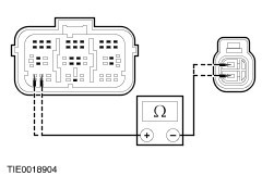
- the air bag control module C423 pin 12, circuit 91S-JA33 (BK/BU) and the 5-way underseat connector C30 pin 6, circuit 91S-JA33 (BK/BU) harness side.
| | | Are the resistances less than 5 ohms? Yes No | | PINPOINT TEST P : DTC B1878: DRIVER SAFETY BELT PRETENSIONER SHORTED TO BATTERY | | TEST CONDITIONS | DETAILS/RESULTS/ACTIONS | | P1: CHECK THE DRIVER SAFETY BELT PRETENSIONER CIRCUIT | WARNING:Wait at least one minute after disconnecting the battery ground lad before disconnecting any supplemental restraint system electrical connector. Failure to follow this instruction may result in personal injury. | | | 1 | | | 2 Ignition switch in position II. | | | 3 Carry out the self-test with the simulators installed . | | | Does the system prove out correctly? Yes No | | P2: CHECK THE DRIVER SAFETY BELT PRETENSIONER CIRCUIT FOR A SHORT TO BATTERY | | | 1 Ignition switch in position 0. | | | 2 Disconnect Air Bag Control Module C423 and C424. | | | 3 Disconnect 5-Way Underseat Air Bag Simulator C30. | | | 4 Ignition switch in position II. | | | 5 Measure the voltage between: - the air bag control module C423 pin 11, circuit 15S-JA33 (GN/BU) and the air bag control module C424 pin 9, circuit 91-JA10 (BK/RD) harness side; and
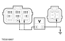
- the air bag control module C423 pin 11, circuit 15S-JA33 (GN/BU) harness side and ground; and
- the air bag control module C423 pin 12, circuit 91S-JA33 (BK/BU) and the air bag control module C424 pin 9, circuit 19-JA10 (BK/RD) harness side; and
- the air bag control module C423 pin 12, circuit 91S-JA33 (BK/BU) harness side and ground.
| | | Is any voltage present? Yes No | | PINPOINT TEST Q : DTC B1879: DRIVER SAFETY BELT PRETENSIONER SHORTED TO GROUND | | TEST CONDITIONS | DETAILS/RESULTS/ACTIONS | | Q1: CHECK THE DRIVER SAFETY BELT PRETENSIONER CIRCUIT | WARNING:Wait at least one minute after disconnecting the battery ground cable before disconnecting any supplemental restraint system electrical connector. Failure to follow this instruction may result in personal injury. | | | 1 | | | 2 Ignition switch in position II. | | | 3 Carry out the self-test with the simulators installed. | | | Does the system prove out correctly? Yes No | | Q2: CHECK THE DRIVER SAFETY BELT PRETENSIONER CIRCUIT FOR A SHORT TO GROUND | | | 1 Ignition switch in position 0. | | | 2 Disconnect Air Bag Control Module C423 and C424. | | | 3 Disconnect 5-Way Underseat Air Bag Simulator C30. | | | 4 Measure the resistance between: - the air bag control module C423 pin 11, circuit 15S-JA33 (GN/BU) and the air bag control module C424 pin 9, circuit 91-JA10 (BK/RD) harness side; and
- the air bag control module C423 pin 11, circuit 15S-JA33 (GN/BU) harness side and ground; and
- the air bag control module C423 pin 12, circuit 91S-JA33 (BK/BU) and the air bag control module C424 pin 9, circuit 91-JA10 (BK/RD) harness side; and
- the air bag control module C423 pin 12, circuit 91S-JA33 (BK/BU) harness side and ground.
| | | Are the resistances greater than 10,000 ohms? Yes No | | PINPOINT TEST R : DTC B1885: DRIVER SAFETY BELT PRETENSIONER LOW RESISTANCE | | TEST CONDITIONS | DETAILS/RESULTS/ACTIONS | | R1: CHECK THE DRIVER SAFETY BELT PRETENSIONER CIRCUIT | WARNING:Wait at least one minute after disconnecting the battery ground cable before disconnecting any supplemental restraint system electrical connector. Failure to follow this instruction may result in personal injury. | | | 1 | | | 2 Ignition switch in position II. | | | 3 Carry out the self-test with the simulators installed. | | | Does the system prove out correctly? Yes No | | R2: CHECK THE DRIVER SAFETY BELT PRETENSIONER CIRCUIT FOR LOW RESISTANCE | | | 1 Ignition switch in position 0. | | | 2 Disconnect Air Bag Control Module C423. | | | 3 Disconnect 5-Way Underseat Air Bag Simulator C30. | | | 4 Measure the resistance between: - the air bag control module C423 pin 11, circuit 15S-JA33 (GN/BU) and pin 12, circuit 91S-JA33 (BK/BU) harness side.
| | | Is the resistance greater than 10,000 ohms? Yes No | | PINPOINT TEST S : DTC B1992: DRIVER SIDE AIR BAG SHORT TO BATTERY | | TEST CONDITIONS | DETAILS/RESULTS/ACTIONS | | S1: CHECK THE DRIVER AIR BAG CIRCUIT | WARNING:Wait at least one minute after disconnecting the battery ground cable before disconnecting any supplemental restraint system electrical connector. Failure to follow this instruction may result in personal injury. | | | 1 | | | 2 Ignition switch in position II. | | | 3 Carry out the self-test with the simulators installed. | | | Does the system prove out correctly? Yes No | | S2: CHECK THE DRIVER SIDE AIR BAG CIRCUIT FOR A SHORT TO BATTERY | | | 1 Ignition switch in position 0. | | | 2 Disconnect Air Bag Control Module C423 and C424. | | | 3 Disconnect Driver Air Bag Simulator C30. | | | 4 Ignition switch in position II. | | | 5 Measure the voltage between: - the air bag control module C423 pin 15, circuit 15S-JA37 (GN/BK) and the air bag control module C424 pin 9, circuit 91-JA10 (BK/RD) harness side; and
- the air bag control module C423 pin 15, circuit 15S-JA37 (GN/BK) harness side and ground; and
- the air bag control module C423 pin 16, circuit 91S-JA37 (BK/GN) and the air bag control module C424 pin 9, circuit 91-JA10 (BK/RD) harness side; and
- the air bag control module C423 pin 16, circuit 91S-JA37 (BK/GN) harness side and ground.
| | | Is any voltage present? Yes No | | PINPOINT TEST T : DTC B1993: DRIVER SIDE AIR BAG CIRCUIT SHORTED TO GROUND. | | TEST CONDITIONS | DETAILS/RESULTS/ACTIONS | | T1: CHECK THE DRIVER SIDE AIR BAG CIRCUIT | WARNING:Wait at least one minute after disconnecting the battery ground cable before disconnecting any supplemental restraint system electrical connector. Failure to follow this instruction may result in personal injury. | | | 1 | | | 2 Ignition switch in position II. | | | 3 Carry out the self-test with the simulators installed. | | | Does the system prove out correctly? Yes No | | T2: CHECK THE DRIVER SIDE AIR BAG CIRCUIT FOR A SHORT TO GROUND. | | | 1 Ignition switch in position 0. | | | 2 Disconnect Air Bag Control Module C423 and C424. | | | 3 Disconnect Driver Side Air Bag Simulator C30. | | | 4 Measure the resistance between: - the air bag control module C423 pin 15, circuit 15S-JA37 (GN/BK) and the air bag control module C424 pin 9, circuit 91-JA10 (BK/RD) harness side; and
- the air bag control module C423 pin 15, circuit 15S-JA37 (GN/BK) harness side and ground; and
- the air bag control module C423 pin 16, circuit 91S-JA37 (BK/GN) and the air bag control module C424 pin 9, circuit 91-JA10 (BK/RD) harness side; and
- the air bag control module C423 pin 16, circuit 91S-JA37 (BK/GN) harness side and ground.
| | | Are the resistances greater than 10,000 ohms? Yes No | | PINPOINT TEST U : DTC B1994: DRIVER SIDE AIR BAG OPEN CIRCUIT OR HIGH RESISTANCE | | TEST CONDITIONS | DETAILS/RESULTS/ACTIONS | | U1: CHECK THE DRIVER SIDE AIR BAG CIRCUIT | WARNING:Wait at least one minute after disconnecting the battery ground cable before disconnecting any supplemental restraint system electrical connector. Failure to follow this instruction may result in personal injury. | | | 1 | | | 2 Ignition switch in position II. | | | 3 Carry out the self-test with the simulators installed. | | | Does the system prove out correctly? Yes No | | U2: CHECK THE DRIVER SIDE AIR BAG FOR OPEN CIRCUIT OR HIGH RESISTANCE | | | 1 Disconnect Air Bag Control Module C423. | | | 2 Disconnect Driver Side Air Bag Simulator C30. | | | 3 Measure the resistance between: - the air bag control module C423 pin 15, circuit 15S-JA37 (GN/BK) and the driver 5-way underseat connector C30 pin 9, circuit 15S-JA37 (GN/BK) harness side; and
- the air bag control module C423 pin 16, circuit 91S-JA37 (BK/GN) and the driver 5-way underseat connector C30 pin 10, circuit 91S-JA37 (BK/GN) harness side.
| | | Are the resistances less than 5 ohms? Yes No | | PINPOINT TEST V : DTC B1995: DRIVER SIDE AIR BAG LOW RESISTANCE | | TEST CONDITIONS | DETAILS/RESULTS/ACTIONS | | V1: CHECK THE DRIVER SIDE AIR BAG CIRCUIT | WARNING:Wait at least one minute after disconnecting the battery ground cable before disconnecting any supplemental restraint system electrical connector. Failure to follow this instruction may result in personal injury. | | | 1 | | | 2 Ignition switch in position II. | | | 3 Carry out the self-test with the simulators installed. | | | Does the system prove out correctly? Yes No | | V2: CHECK THE DRIVER SIDE AIR BAG CIRCUIT FOR LOW RESISTANCE | | | 1 Ignition switch in position 0. | | | 2 Disconnect Air Bag Control Module C423. | | | 3 Disconnect 5-Way Underseat Air Bag Simulator C30. | | | 4 Measure the resistance between: - the air bag control module C423 pin 15, circuit 15S-JA37 (GN/BK) and pin 16, circuit 91S-JA37 (BK/GN) harness side.
| | | Is the resistance greater than 10,000 ohms? Yes No | | PINPOINT TEST W : DTC B2117: DRIVER SIDE AIR BAG MODULE CIRCUIT CAPACITANCE OUT OF RANGE | | TEST CONDITIONS | DETAILS/RESULTS/ACTIONS | | W1: CHECK THE DRIVER SIDE AIR BAG MODULE CAPACITANCE | WARNING:Wait at least one minute after disconnecting the battery ground cable before disconnecting any supplemental restraint system electrical connector. Failure to follow this instruction may result in personal injury. | | | 1 | | | 2 Ignition switch in position II. | | | 3 Carry out the self-test with the simulators installed. | | | Does the system prove out correctly? Yes No | | PINPOINT TEST X : DTC B2444: DRIVER SIDE IMPACT SENSOR SHORTED TO GROUND/IGNITION/BATTERY OR INTERNAL FAULT | | TEST CONDITIONS | DETAILS/RESULTS/ACTIONS | | X1: CHECK THE DRIVER SIDE IMPACT SENSOR CIRCUIT | WARNING:Wait at least one minute after disconnecting the battery ground cable before disconnecting any supplemental restraint system electrical connector. Failure to follow this instruction may result in personal injury. | | | 1 | | | 2 Disconnect Side Impact Sensor C427 or C428. | | | 3 Disconnect Air Bag Control Module C423. | | | 4 Measure the resistance between: - the air bag control module C423 pin 18, circuit 15S-JA39 (GN/YE) and the driver side impact sensor C427 pin 1, circuit 15S-JA39 (GN/YE) harness side; and
- the air bag control module C423 pin 19, circuit 91-JA39 (BK/YE) and the driver side impact sensor C427 pin 2, circuit 91-JA39 (BK/YE) harness side.
- the air bag control module C423 pin 18, circuit 15S-JA39 (GN/YE) and the driver side impact sensor C428 pin 1, circuit 15S-JA39 (GN/YE) harness side; and
- the air bag control module C423 pin 19, circuit 91-JA39 (BK/YE) and the driver side impact sensor C428 pin 2, circuit 91-JA39 (BK/YE) harness side.
| | | Are the resistances less than 5 ohms? Yes No | | X2: CHECK THE DRIVER SIDE IMPACT SENSOR CIRCUIT FOR A SHORT CIRCUIT | | | 1 Disconnect Air Bag Control Module C424. | | | 2 Measure the resistance between: - the air bag control module C423 pin 18, circuit 15S-JA39 (GN/YE) and the air bag control module C424 pin 8, circuit 15-JA10 (GN/OG) harness side; and
- the air bag control module C423 pin 18, circuit 15S-JA39 (GN/YE) and the air bag control module C424 pin 9, circuit 91-JA10 (BK/RD) harness side; and
- the air bag control module C423 pin 18, circuit 15S-JA39 (GN/YE) harness side and ground; and
- the air bag control module C423 pin 19, circuit 91-JA39 (BK/YE) and the air bag control module C424 pin 8, circuit 15-JA10 (GN/OG) harness side; and
- the air bag control module C423 pin 19, circuit 91-JA39 (BK/YE) and the air bag control module C424 pin 9, circuit 91-JA10 (BK/RD) harness side; and
- the air bag control module C423 pin 19, circuit 91-JA39 (BK/YE) harness side and ground.
| | | Are the resistances greater than 10,000 ohms? Yes No | | PINPOINT TEST Y : DTC B1880: PASSENGER SAFETY BELT PRETENSIONER CIRCUIT CAPACITANCE OUT OF RANGE | | TEST CONDITIONS | DETAILS/RESULTS/ACTIONS | | Y1: CHECK THE PASSENGER SAFETY BELT PRETENSIONER CAPACITANCE | WARNING:Wait at least one minute after disconnecting the battery ground cable before disconnecting any supplemental restraint system electrical connector. Failure to follow this instruction may result in personal injury. | | | 1 | | | 2 Ignition switch in position II. | | | 3 Carry out the self-test with the simulators installed. | | | Does the system prove out correctly? Yes No | | PINPOINT TEST Z : DTC 1881: PASSENGER SAFETY BELT PRETENSIONER OPEN CIRCUIT OR HIGH RESISTANCE | | TEST CONDITIONS | DETAILS/RESULTS/ACTIONS | | Z1: CHECK THE PASSENGER SAFETY BELT PRETENSIONER CIRCUIT | WARNING:Wait at least one minute after disconnecting the battery ground cable before disconnecting any supplemental restraint system electrical connector. Failure to follow this instruction may result in personal injury. | | | 1 | | | 2 Ignition switch in position II. | | | 3 Carry out the self-test with the simulators installed. | | | Does the system prove out correctly? Yes No | | Z2: CHECK THE PASSENGER SAFETY BELT PRETENSIONER FOR OPEN CIRCUIT OR HIGH RESISTANCE | | | 1 Ignition switch in position 0. | | | 2 Disconnect Air Bag Control Module C423. | | | 3 Disconnect 5-Way Underseat Air Bag Simulator C31. | | | 4 Measure the resistance between: - the air bag control module C423 pin 20, circuit 15S-JA34 (GN/OG) and the passenger 5-way underseat connector C31 pin 5, 15S-JA34 (GN/OG) harness side; and
- the air bag control module C423 pin 21, circuit 91S-JA34 (BK/RD) and the passenger 5-way underseat connector C31 pin 6, 91S-JA34 (BK/RD) harness side.
| | | Are the resistances less than 5 ohms? Yes No | | PINPOINT TEST AA : DTC B1882: PASSENGER SAFETY BELT PRETENSIONER SHORTED TO BATTERY | | TEST CONDITIONS | DETAILS/RESULTS/ACTIONS | | AA1: CHECK THE PASSENGER SAFETY BELT PRETENSIONER CIRCUIT | WARNING:Wait at least one minute after disconnecting the battery ground cable before disconnecting any supplemental restraint system electrical connector. Failure to follow this instruction may result in personal injury. | | | 1 | | | 2 Ignition switch in position II. | | | 3 Carry out the self-test with the simulators installed. | | | Does the system prove out correctly? Yes No | | AA2: CHECK THE PASSENGER SAFETY BELT PRETENSIONER CIRCUIT FOR A SHORT TO BATTERY | | | 1 Ignition switch in position 0. | | | 2 Disconnect Air Bag Control Module C423. | | | 3 Disconnect 5-Way Underseat Air Bag Simulator C31. | | | 4 Ignition switch in position II. | | | 5 Measure the voltage between: - the air bag control module C423 pin 20, circuit 15S-JA34 (GN/OG) and the air bag control module C424 pin 9, circuit 91-JA10 (BK/RD) harness side; and
- the air bag control module C423 pin 20, circuit 15S-JA34 (GN/OG) harness side and ground; and
- the air bag control module C423 pin 21, circuit 91S-JA34 (BK/RD) and the air bag control module C424 pin 9, circuit 91-JA10 (BK/RD) harness side; and
- the air bag control module C423 pin 21, circuit 91S-JA34 (BK/RD) harness side and ground
| | | Is any voltage present? Yes No | | PINPOINT TEST AB : DTC B1883: PASSENGER SAFETY BELT PRETENSIONER SHORTED TO GROUND | | TEST CONDITIONS | DETAILS/RESULTS/ACTIONS | | AB1: CHECK THE PASSENGER SAFETY BELT PRETENSIONER CIRCUIT | WARNING:Wait at least one minute after disconnecting the battery ground cable before disconnecting any supplemental restraint system electrical connector. Failure to follow this instruction may result in personal injury. | | | 1 | | | 2 Ignition switch in position II. | | | 3 Carry out the self-test with the simulators installed. | | | Does the system prove out correctly? Yes No | | AB2: CHECK THE PASSENGER SAFETY BELT PRETENSIONER CIRCUIT FOR A SHORT TO GROUND | | | 1 Ignition switch in position 0. | | | 2 Disconnect Air Bag Control Module C423 and C424. | | | 3 Disconnect 5-Way Underseat Air Bag Simulator C31. | | | 4 Measure the resistance between: - the air bag control module C423 pin 20, circuit 15S-JA34 (GN/OG) and the air bag control module C424 pin 9, circuit 91-JA10 (BK/RD) harness side; and
- the air bag control module C423 pin 20, circuit 15S-JA34 (GN/OG) harness side and ground; and
- the air bag control module C423 pin 21, circuit 91S-JA34 (BK/RD) and the air bag control module C424 pin 9, circuit 91-JA10 (BK/RD) harness side; and
- the air bag control module C423 pin 21, circuit 91S-JA34 (BK/RD) harness side and ground
| | | Are the resistances greater than 10,000 ohms? Yes No | | PINPOINT TEST AC : DTC B1886: PASSENGER SAFETY BELT PRETENSIONER LOW RESISTANCE | | TEST CONDITIONS | DETAILS/RESULTS/ACTIONS | | AC1: CHECK THE PASSENGER SAFETY BELT PRETENSIONER CIRCUIT | WARNING:Wait at least one minute after disconnecting the battery ground cable before disconnecting any supplemental restraint system electrical connector. Failure to follow this instruction may result in personal injury. | | | 1 | | | 2 Ignition switch in position II. | | | 3 Carry out the self-test with the simulators installed | | | Does the system prove out correctly? Yes No | | AC2: CHECK THE PASSENGER SAFETY BELT PRETENSIONER CIRCUIT FOR LOW RESISTANCE | | | 1 Ignition switch in position 0. | | | 2 Disconnect Air Bag Control Module C423. | | | 3 Disconnect 5-Way Underseat Air Bag Simulator C31. | | | 4 Measure the resistance between: - the air bag control module C423 pin 20, circuit 15S-JA34 (GN/OG) and pin 21, circuit 91S-JA34 (BK/RD) harness side.
| | | Is the resistance greater than 10,000 ohms? Yes No | | PINPOINT TEST AD : DTC 1996 PASSENGER SIDE AIR BAG SHORT TO BATTERY. | | TEST CONDITIONS | DETAILS/RESULTS/ACTIONS | | AD1: CHECK THE PASSENGER AIR BAG CIRCUIT | WARNING:Wait at least one minute after disconnecting the battery ground cable before disconnecting any supplemental restraint system electrical connector. Failure to follow this instruction may result in personal injury. | | | 1 | | | 2 Ignition switch in position II. | | | 3 Carry out the self-test with simulators installed. | | | Does the system prove out correctly? Yes No | | AD2: CHECK THE PASSENGER SIDE AIR BAG CIRCUIT FOR A SHORT TO BATTERY | | | 1 Ignition switch in position 0. | | | 2 Disconnect Air Bag Control Module C423 and C424. | | | 3 Disconnect 5-Way Underseat Air Bag Simulator C31. | | | 4 Ignition switch in position II. | | | 5 Measure the voltage between: - the air bag control module C423 pin 23, circuit 15S-JA15 (GN/RD) and the air bag control module C424 pin 9, circuit 91-JA10 (BK/RD) harness side; and
- the air bag control module C423 pin 23, circuit 15S-JA15 (GN/RD) harness side and ground; and
- the air bag control module C423 pin 24, circuit 91S-JA15 (BK/OG) and the air bag control module C424 pin 9, circuit 91-JA10 (BK/RD) harness side; and
- the air bag control module C423 pin 24, circuit 91S-JA15 (BK/OG) harness side and ground.
- the air bag control module C423 pin 23, circuit 15S-JA38 (GN/OG) and the air bag control module C424 pin 9, circuit 91-JA10 (BK/RD) harness side; and
- the air bag control module C423 pin 23, circuit 15S-JA38 (GN/OG) harness side and ground; and
- the air bag control module C423 pin 24, circuit 91S-JA38 (BK/RD) and the air bag control module C424 pin 9, circuit 91-JA10 (BK/RD) harness side; and
- the air bag control module C423 pin 24, circuit 91S-JA38 (BK/RD) harness side and ground.
| | | Is any voltage present? Yes No | | PINPOINT TEST AE : DTC B1997: PASSENGER SIDE AIR BAG CIRCUIT SHORTED TO GROUND | | TEST CONDITIONS | DETAILS/RESULTS/ACTIONS | | AE1: CHECK THE PASSENGER SIDE AIR BAG CIRCUIT | WARNING:Wait at least one minute after disconnecting the battery ground cable before disconnecting any supplemental restraint system electrical connector. Failure to follow this instruction may result in personal injury. | | | 1 | | | 2 Ignition switch in position II. | | | 3 Carry out the self-test with simulators installed. | | | Does the system prove out correctly? Yes No | | AE2: CHECK THE PASSENGER SIDE AIR BAG FOR A SHORT TO GROUND | | | 1 Ignition switch in position II. | | | 2 Disconnect Air Bag Control Module C423 and C424. | | | 3 Disconnect 5-Way Underseat Air Bag Simulator C31. | | | 4 Measure the resistance between: - the air bag control module C423 pin 23, circuit 15S-JA15 (GN/RD) and the air bag control module C424 pin 9, circuit 91-JA10 (BK/RD) harness side; and
- the air bag control module C423 pin 23, circuit 15S-JA15 (GN/RD) harness side and ground; and
- the air bag control module C423 pin 24, circuit 91S-JA15 (BK/OG) and the air bag control module C424 pin 9, circuit 91-JA10 (BK/RD) harness side; and
- the air bag control module C423 pin 24, circuit 91S-JA15 (BK/OG) harness side and ground.
- the air bag control module C423 pin 23, circuit 15S-JA38 (GN/OG) and the air bag control module C424 pin 9, circuit 91-JA10 (BK/RD) harness side; and
- the air bag control module C423 pin 23, circuit 15S-JA38 (GN/OG) harness side and ground; and
- the air bag control module C423 pin 24, circuit 91S-JA38 (BK/RD) and the air bag control module C424 pin 9, circuit 91-JA10 (BK/RD) harness side; and
- the air bag control module C423 pin 24, circuit 91S-JA38 (BK/RD) harness side and ground.
| | | Are the resistances greater than 10,000 ohms? Yes No | | PINPOINT TEST AF : DTC B1998: PASSENGER SIDE AIR BAG OPEN CIRCUIT OR HIGH RESISTANCE | | TEST CONDITIONS | DETAILS/RESULTS/ACTIONS | | AF1: CHECK THE PASSENGER SIDE AIR BAG CIRCUIT | WARNING:Wait at least one minute after disconnecting the battery ground cable before disconnecting any supplemental restraint system electrical connector. Failure to follow this instruction may result in personal injury. | | | 1 | | | 2 Ignition switch in position II. | | | 3 Carry out the self-test with the simulators installed. | | | Does the system prove out correctly? Yes No | | AF2: CHECK THE PASSENGER SIDE AIR BAG FOR OPEN CIRCUIT OR HIGH RESISTANCE | | | 1 Disconnect Air Bag Control Module C423. | | | 2 Disconnect 5-Way Underseat Air Bag Simulator C31. | | | 3 Measure the resistance between: - the air bag control module C423 pin 23, circuit 15S-JA15 (GN/RD) and the passenger 5-way underseat connector C31 pin 9, 15S-JA15 (GN/RD) harness side; and
- the air bag control module C423 pin 24, circuit 91S-JA15 (BK/OG) and the passenger 5-way underseat connector C31 pin 10, 91S-JA15 (BK/OG) harness side.
- the air bag control module C423 pin 23, circuit 15S-JA38 (GN/OG) and the passenger 5-way underseat connector C31 pin 9, 15S-JA38 (GN/OG) harness side; and
- the air bag control module C423 pin 24, circuit 91S-JA38 (BK/RD) and the passenger 5-way underseat connector C31 pin 10, 91S-JA38 (BK/RD) harness side.
| | | Are the resistances less than 5 ohms? Yes No | | PINPOINT TEST AG : DTC B1999 PASSENGER SIDE AIR BAG LOW RESISTANCE | | TEST CONDITIONS | DETAILS/RESULTS/ACTIONS | | AG1: CHECK THE PASSENGER SIDE AIR BAG CIRCUIT | WARNING:Wait at least one minute after disconnecting the battery ground cable before disconnecting any supplemental restraint system electrical connector. Failure to follow this instruction may result in personal injury. | | | 1 | | | 2 Ignition switch in position II. | | | 3 Carry out the self-test with the simulators installed. | | | Does the system prove out correctly? Yes No | | AG2: CHECK THE PASSENGER SIDE AIR BAG FOR LOW RESISTANCE | | | 1 Ignition switch in position 0. | | | 2 Disconnect Air Bag Control Module C423. | | | 3 Disconnect 5-Way Underseat Side Air Bag Simulator C31. | | | 4 Measure the resistance between: - the air bag control module C423 pin 23, circuit 15S-JA15 (GN/RD) and pin 24, circuit 91S-JA15 (BK/OG) harness side.
- the air bag control module C423 pin 23, circuit 15S-JA38 (GN/OG) and pin 24, circuit 91S-JA38 (BK/RD) harness side.
| | | Is the resistance greater than 10,000 ohms? Yes No | | PINPOINT TEST AH : DTC B2118: PASSENGER SIDE AIR BAG MODULE CIRCUIT CAPACITANCE OUT OF RANGE | | TEST CONDITIONS | DETAILS/RESULTS/ACTIONS | | AH1: CHECK THE PASSENGER SIDE AIR BAG MODULE CAPACITANCE | WARNING:Wait at least one minute after disconnecting the battery ground cable before disconnecting any supplemental restraint system electrical connector. Failure to follow this instruction may result in personal injury. | | | 1 | | | 2 Ignition switch in position II. | | | 3 Carry out the self-test with the simulators installed. | | | Does the system prove out correctly? Yes No | | PINPOINT TEST AI : DTC B2445: PASSENGER SIDE IMPACT SENSOR SHORTED TO GROUND/IGNITION/BATTERY OR INTERNAL FAULT | | TEST CONDITIONS | DETAILS/RESULTS/ACTIONS | | AI1: CHECK THE PASSENGER SIDE IMPACT SENSOR CIRCUIT | WARNING:Wait at least one minute after disconnecting the battery ground cable before disconnecting any supplemental restraint system electrical connectors. Failure to follow this instruction may result in personal injury. | | | 1 | | | 2 Disconnect Side Impact Sensor C427 or C428. | | | 3 Disconnect Air Bag Control Module C423. | | | 4 Measure the resistance between: - the air bag control module C423 pin 26, circuit 15S-JA40 (GN/WH) and the side impact sensor C428 pin 1, circuit 15S-JA40 (GN/WH) harness side; and
- the air bag control module C423 pin 25, circuit 91-JA40 (BK/WH) and the side impact sensor C428 pin 2, circuit 91-JA40 (BK/WH) harness side.
- the air bag control module C423 pin 26, circuit 15S-JA40 (GN/WH) and the side impact sensor C427 pin 1, circuit 15S-JA40 (GN/WH) harness side; and
- the air bag control module C423 pin 25, circuit 91-JA40 (BK/WH) and the side impact sensor C427 pin 2, circuit 91-JA40 (BK/WH) harness side.
| | | Are the resistances less than 5 ohms? Yes No | | AI2: CHECK THE PASSENGER SIDE IMPACT SENSOR CIRCUIT FOR A SHORT CIRCUIT | | | 1 Disconnect Air Bag Control Module C424. | | | 2 Measure the resistance between: - the air bag control module C423 pin 26, circuit 15S-JA40 (GN/WH) and the air bag control module C424 pin 8, circuit 15-JA10 (GN/OG) harness side; and
- the air bag control module C423 pin 26, circuit 15S-JA40 (GN/WH) and the air bag control module C424 pin 9, circuit 91-JA10 (BK/RD) harness side; and
- the air bag control module C423 pin 26, circuit 15S-JA40 (GN/WH) harness side and ground; and
- the air bag control module C423 pin 25, circuit 91S-JA40 (BK/WH) and the air bag control module C424 pin 8, circuit 15-JA10 (GN/OG) harness side; and
- the air bag control module C423 pin 25, circuit 91S-JA40 (BK/WH) and the air bag control module C424 pin 9, circuit 91-JA10 (BK/RD) harness side; and
- the air bag control module C423 pin 25, circuit 91S-JA40 (BK/WH) harness side and ground.
| | | Are the resistances greater than 10,000 ohms? Yes No | | |