| PINPOINT TEST B : ONE OR MORE PARKING LAMPS, REAR LAMPS OR LICENSE PLATE LAMPS ARE INOPERATIVE |
| TEST CONDITIONS | DETAILS/RESULTS/ACTIONS |
| B1: DETERMINE THE FAULT CONDITION |
| | 1 A failure of the license plate lamps is not necessarily caused by an electrical defect. Due to a high level of heat emitted from the bulb in the – license plate lamp, the gasket for the – license plate lamp may become deformed or melt. If there is a problem, a comprehensive visual inspection of the license plate lamp or the tailgate handle should first be performed, looking in particular for any traces of corrosion caused by the penetration of water. |
| | Can traces of corrosion be seen in the area of the license plate lamp? Yes Install modified gaskets for the license plate lamps. Check the operation of the system. No |
| B2: DETERMINE THE FAULT CONDITION |
| | 1 SWITCH ON the side lights. |
| | 2 DETERMINE the fault conditions. |
| | Is one left-hand parking lamp and/or the license plate lamp(s) inoperative? Yes - Front left-hand parking lamp (all other lamps OK): GO to B5. - Front left-hand parking lamp and left-hand rear lamp: GO to B3. - Left-hand rear lamp (all other lamps OK): GO to B11. - Licence plate lamp(s) (all other lamps OK): GO to B17. No - Front right-hand parking lamp (all other lamps OK): GO to B8. - Front right-hand parking lamp and rear right-hand lamp: GO to B4. - Right-hand rear lamp (all other lamps OK): GO to B14. |
| B3: CHECK FUSE F22 (7.5 A) (CJB). |
| | 1 Ignition switch in position 0. |
| | 2 Disconnect fuse F22 (7.5 A) (CJB). |
| | 3 CHECK fuse F22 (7.5 A) (CJB). |
| | Is the fuse OK? Yes CHECK and if necessary RENEW the CJB. CHECK the operation of the system. No RENEW fuse F22 (7.5 A) (CJB). If the fuse blows again, LOCATE and RECTIFY the short to ground using the Wiring Diagrams. CHECK the operation of the system. |
| B4: CHECK FUSE F23 (7.5 A) (CJB). |
| | 1 Ignition switch in position 0. |
| | 2 Disconnect fuse F23 (7.5 A) (CJB). |
| | 3 CHECK fuse F23 (7.5 A) (CJB). |
| | Is the fuse OK? Yes CHECK and if necessary RENEW the CJB. CHECK the operation of the system. No RENEW fuse F23 (7.5 A) (CJB). If the fuse blows again, LOCATE and RECTIFY the short to ground using the Wiring Diagrams. CHECK the operation of the system. |
| B5: CHECK LEFT-HAND HEADLAMP |
| | 1 Ignition switch in position II. |
| | 2 SWITCH ON the left-hand turn signal. |
| | 3 CHECK left-hand turn signal lamp |
| | Does left-hand turn signal operate? Yes No |
| B6: CHECK VOLTAGE AT THE FRONT LEFT-HAND PARKING LAMP |
| | 1 Ignition switch in position 0. |
| | 2 Disconnect left-hand headlamp from connector C416. |
| | 3 SWITCH ON the side lights. |
| | 4 Measure the voltage at left-hand headlamp, connector C416, between pin 4, circuit 29S-LF7 (OG/BU), wiring harness side and ground. |
| | Does the meter display battery voltage? Yes CHECK and if necessary RENEW the headlamp. CHECK the operation of the system. No LOCATE and RECTIFY the break in the circuit between fuse F22 (7.5 A) (CJB) and the left-hand headlamp using the Wiring Diagrams. CHECK the operation of the system. |
| B7: CHECK GROUND CONNECTION AT LEFT-HAND HEADLAMP |
| | 1 Ignition switch in position 0. |
| | 2 Disconnect left-hand headlamp from connector C416. |
| | 3 Measure the resistance between the left-hand headlamp, connector C416, pin 6, circuit 31-LE31 (BK), wiring harness side and ground. |
| | Is a resistance of less than 2 ohms registered? Yes CHECK and if necessary RENEW the headlamp. CHECK the operation of the system. No LOCATE and RECTIFY the break in the circuit between the left-hand headlamp and soldered connection S10 using the wiring diagrams. CHECK the operation of the system. |
| B8: CHECK THE RIGHT-HAND HEADLAMP |
| | 1 Ignition switch in position II. |
| | 2 SWITCH ON the right-hand turn signal. |
| | 3 CHECK right-hand turn signal lamp. |
| | Does right-hand turn signal work? Yes No |
| B9: CHECK VOLTAGE AT THE FRONT RIGHT-HAND PARKING LAMP |
| | 1 Ignition switch in position 0. |
| | 2 Disconnect right-hand headlamp from connector C422. |
| | 3 SWITCH ON the side lights. |
| | 4 Test voltage between right-hand headlamp connector C422, pin 4, circuit 29S-LF16 (OG/GN), wiring harness side and ground. |
| | Does the meter display battery voltage? Yes CHECK and if necessary RENEW the headlamp. CHECK the operation of the system. No LOCATE and RECTIFY the break in the circuit between fuse F23 (7.5 A) (CJB) and the right-hand headlamp using the Wiring Diagrams. CHECK the operation of the system. |
| B10: CHECK GROUND CONNECTION AT THE RIGHT-HAND HEADLAMP |
| | 1 Ignition switch in position 0. |
| | 2 Disconnect right-hand headlamp from connector C422. |
| | 3 Measure the resistance between the right-hand headlamp, connector C422, pin 6, circuit 31-LE30 (BK), wiring harness side and ground. |
| | Is a resistance of less than 2 ohms registered? Yes CHECK and if necessary RENEW the headlamp. CHECK the operation of the system. No LOCATE and RECTIFY the break in the circuit between the right-hand headlamp and soldered connection S11 using the wiring diagrams. CHECK the operation of the system. |
| B11: CHECK THE LEFT-HAND REAR LAMP ASSEMBLY |
| | 1 Ignition switch in position II. |
| | 2 SWITCH ON the left-hand turn signal. |
| | 3 Check left-hand rear turn signal lamp. |
| | Is the left-hand rear turn signal operative? Yes No |
| B12: CHECK THE VOLTAGE AT THE LEFT-HAND REAR LAMP ASSEMBLY |
| | 1 Ignition switch in position 0. |
| | 2 Disconnect Left-hand rear lamp assembly. - Vehicles without trailer socket: from connector C333
- Vehicles with trailer socket: from connector C333a
|
| | 3 SWITCH ON the side lights. |
| | 4 Measure the voltage at the left-hand rear lamp assembly, vehicles built before 08/2005: - Vehicles without trailer socket, built before 08/2005: connector C333, between pin 1, circuit 29S-LF11 (OG/WH), wiring harness side and ground.
- Vehicles with trailer socket, built before 03/2004: connector C333a, between pin 1, circuit (GY/BK), wiring harness side and ground.
- Vehicles with trailer socket, built from 03/2004 to 08/2005: connector C333a, between pin 1, circuit (OG/WH), wiring harness side and ground.
|
| | 5 Measure the voltage at the left-hand rear lamp assembly, vehicles built from 08/2005: - Vehicles without trailer socket: connector C333, between pin 2, circuit 29S-LF11 (OG/WH), wiring harness side and ground.
- Vehicles with trailer socket: connector C333a, between pin 2, circuit (OG/WH), wiring harness side and ground.
|
| | Does the meter display battery voltage? Yes CHECK and if necessary RENEW the rear lamp assembly. CHECK the operation of the system. No LOCATE and RECTIFY the break in the circuit between fuse F22 (7.5 A) (CJB) and the rear lamp assembly using the Wiring Diagrams. CHECK the operation of the system. |
| B13: CHECK THE GROUND CONNECTION OF THE LEFT-HAND REAR LAMP ASSEMBLY |
| | 1 Ignition switch in position 0. |
| | 2 Disconnect Left-hand rear lamp assembly. - Vehicles without trailer socket: from connector C333
- Vehicles with trailer socket: from connector C333a
|
| | 3 Measure the resistance between the left-hand rear lamp assembly, vehicles built before 08/2005: - Vehicles without trailer socket: Connector C333, pin 4, circuit 31-LF23 (BK), wiring harness side and ground.
- Vehicles with 13-pin trailer socket, built from 03/2004: Connector C333a, pin 4, circuit (BN), wiring harness side and ground.
- All other vehicles with trailer socket: connector C333a, pin 4, circuit (GN), wiring harness side and ground.
|
| | 4 Measure the resistance between the left-hand rear lamp assembly, vehicles built from 08/2005: - Vehicles without trailer socket: Connector C333, pin 4, circuit 31-LF23 (BK), wiring harness side and ground.
- Vehicles with 13-pin trailer socket: Connector C333a, pin 4, circuit (BN), wiring harness side and ground.
- All other vehicles with trailer socket: connector C333a, pin 4, circuit (GN), wiring harness side and ground.
|
| | Is a resistance of less than 2 ohms registered? Yes CHECK and if necessary RENEW the rear lamp assembly. CHECK the operation of the system. No - Vehicles without trailer socket: LOCATE and RECTIFY the break in circuit 31-LF23 (BK) between the rear lamp assembly and soldered connection S24 using the Wiring Diagrams. CHECK the operation of the system. - Vehicles with 13-pin trailer socket, built from 03/2004: LOCATE and RECTIFY the break in the circuit (BN) between the rear lamp assembly and soldered connection S1008 using the Wiring Diagrams. CHECK the operation of the system. - All other vehicles with trailer socket: LOCATE and RECTIFY the break in circuit(s) (GN) or 31-LF23 (BK) between the rear lamp assembly and soldered connection S24 using the Wiring Diagrams. CHECK the operation of the system. |
| B14: CHECK THE RIGHT-HAND REAR LAMP ASSEMBLY |
| | 1 Ignition switch in position II. |
| | 2 SWITCH ON the right-hand turn signal. |
| | 3 CHECK right-hand turn signal lamp. |
| | Does right-hand turn signal work? Yes No |
| B15: CHECK THE VOLTAGE AT THE RIGHT-HAND REAR LAMP ASSEMBLY |
| | 1 Ignition switch in position 0. |
| | 2 Disconnect Right-hand rear lamp assembly. - Vehicles without trailer socket: from connector C348
- Vehicles with trailer socket: from connector C348a
|
| | 3 SWITCH ON the side lights. |
| | 4 Measure the voltage at the right-hand rear lamp assembly, vehicles built before 08/2005: - Vehicles without trailer socket: connector C348, between pin 1, circuit 29S-LF20 (OG), wiring harness side and ground.
- Vehicles with trailer socket, built before 03/2004: connector C348a, between pin 1, circuit (GY/RD), wiring harness side and ground.
- Vehicles with trailer socket, built from 03/2004 to 08/2005: connector C348a, between pin 1, circuit (OG), wiring harness side and ground.
|
| | 5 Measure the voltage at the right-hand rear lamp assembly, vehicles built from 08/2005: - Vehicles without trailer socket: connector C348, between pin 2, circuit 29S-LF20 (OG), wiring harness side and ground.
- Vehicles with trailer socket: connector C348a, between pin 2, circuit (OG), wiring harness side and ground.
|
| | Does the meter display battery voltage? Yes CHECK and if necessary RENEW the rear lamp assembly. CHECK the operation of the system. No LOCATE and RECTIFY the break in the circuit(s) between fuse F23 (7.5 A) (CJB) and the rear lamp assembly using the Wiring Diagrams. CHECK the operation of the system. |
| B16: CHECK THE GROUND CONNECTION OF THE RIGHT-HAND REAR LAMP ASSEMBLY |
| | 1 Ignition switch in position 0. |
| | 2 Disconnect Right-hand rear lamp assembly. - Vehicles without trailer socket: from connector C348
- Vehicles with trailer socket: from connector C348a
|
| | 3 Measure the resistance between the right-hand rear lamp assembly, vehicles built before 08/2005: - Vehicles without trailer socket: Connector C348, between pin 4, circuit 31-LF24 (BK), wiring harness side and ground.
- Vehicles with trailer socket, built before 03/2004: connector C348a, between pin 4, circuit (BK), wiring harness side and ground.
- Vehicles with trailer socket built from 03/2004: connector C348a, between pin 4, circuit (BN), wiring harness side and ground.
|
| | 4 Measure the resistance between the right-hand rear lamp assembly, vehicles built from 08/2005: - Vehicles without trailer socket: Connector C348, between pin 4, circuit 31-LF24 (BK), wiring harness side and ground.
- Vehicles with trailer socket: connector C348a, between pin 4, circuit (BN), wiring harness side and ground.
|
| | Is a resistance of less than 2 ohms registered? Yes CHECK and if necessary RENEW the rear lamp assembly. CHECK the operation of the system. No LOCATE and RECTIFY the break in the circuit(s) between the rear lamp assembly and ground connection G18 using the Wiring Diagrams. CHECK the operation of the system. |
| B17: DETERMINE THE FAULT CONDITION |
| | 1 Ignition switch in position II. |
| | 2 SWITCH ON the side lights. |
| | Are both license plate lamps inoperative? Yes No - Left-hand license plate lamp is inoperative: GO to B21. - Right-hand license plate lamp is inoperative: GO to B22. |
| B18: CHECK FUSE F33 (7.5 A) (CJB). |
| | 1 Ignition switch in position 0. |
| | 2 Disconnect fuse F33 (7.5 A) (CJB). |
| | 3 CHECK Fuse F33 (7.5 A) (CJB). |
| | Is the fuse OK? Yes No RENEW fuse F33 (7.5 A) (CJB). If the fuse blows again, LOCATE and RECTIFY the short to ground using the Wiring Diagrams. CHECK the operation of the system. |
| B19: CHECK THE VOLTAGE AT FUSE F33 (7.5 A) (CJB) |
| | 1 Connect fuse F33 (7.5 A) (CJB). |
| | 2 Ignition switch in position II. |
| | 3 SWITCH ON the side lights. |
| | 4 Measure the voltage between fuse F33 (7.5 A) and ground. |
| | Does the meter display battery voltage? Yes No LOCATE and RECTIFY the break in the voltage supply to fuse F33 (7.5 A) (CJB) using the Wiring Diagrams, if necessary CHECK and RENEW the CJB. CHECK the operation of the system. |
| B20: TEST THE VOLTAGE SUPPLY OF THE LICENSE PLATE LAMPS |
| | 1 Ignition switch in position 0. |
| | 2 Disconnect right-hand license plate lamp from connector C760. |
| | 3 SWITCH ON the side lights. |
| | 4 Measure the voltage between the right-hand license plate lamp, connector C760, pin 1, circuit 29S-LF22 (OG/BK), wiring harness side and ground. |
| | Does the meter display battery voltage? Yes LOCATE and RECTIFY the break in circuit 31-DA25 (BK) between soldered connection S201 and soldered connection S24 using the Wiring Diagrams. CHECK the operation of the system. No LOCATE and RECTIFY the break in the circuit(s) between fuse F33 (7.5 A) (CJB) and the left-hand license plate lamp using the Wiring Diagrams. CHECK the operation of the system. |
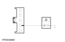
| B21: CHECK GROUND CONNECTION OF LEFT-HAND LICENSE PLATE LAMP |
| | 1 Ignition switch in position 0. |
| | 2 Disconnect left-hand license plate lamp from connector C759. |
| | 3 Measure the resistance between the left-hand license lamp, connector C759, pin 1, circuit 31-LF21 (BK), wiring harness side and ground. |
| | Is a resistance of less than 2 ohms registered? Yes CHECK and if necessary RENEW the license plate lamp. CHECK the operation of the system. No LOCATE and RECTIFY the break in the circuit between the license plate lamp and soldered connection S201 using the wiring diagrams. Check the operation of the system. |
| B22: CHECK VOLTAGE SUPPLY TO RIGHT-HAND LICENSE PLATE LAMP |
| | 1 Ignition switch in position 0. |
| | 2 Disconnect right-hand license plate lamp from connector C760. |
| | 3 Ignition switch in position II. |
| | 4 SWITCH ON the side lights. |
| | 5 Measure the voltage between the right-hand license plate lamp, connector C760, pin 1, circuit 29S-LF22 (OG/BK), wiring harness side and ground. |
| | Is battery voltage measured? Yes No LOCATE and RECTIFY the break in the circuit between the left-hand license plate lamp and the right-hand license plate lamp using the wiring diagrams. Check the operation of the system. |
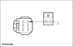
| B23: CHECK GROUND CONNECTION OF RIGHT-HAND LICENSE PLATE LAMP |
| | 1 Ignition switch in position 0. |
| | 2 Disconnect right-hand license plate lamp from connector C761. |
| | 3 Measure the resistance between the right-hand license plate lamp, connector C761, pin 1, circuit 31-LF22 (BK), wiring harness side and ground. |
| | Is a resistance of less than 2 ohms registered? Yes CHECK and INSTALL A NEW license plate lamp. CHECK the operation of the system. No LOCATE and RECTIFY the break in the circuit between the right-hand license plate lamp and soldered connection S201 using the wiring diagrams. Check the operation of the system. |