| PINPOINT TEST B : ONE OR MORE STOP LAMPS ARE INOPERATIVE |
| TEST CONDITIONS | DETAILS/RESULTS/ACTIONS |
| B1: DETERMINE THE FAULT CONDITION |
| | 1 Ignition switch in position 0. |
| | 2 Disconnect stop lamp switch from connector C355. |
| | 3 Vehicles built before 10/2004: Connect a fused jumper wire (15 A) at the stop lamp switch, connector C355, between pin 1, circuit 15-LG23 (GN/WH) and pin 3, circuit 15S-DA12 (GN/WH), wiring harness side. |
| | 4 Vehicles built from 10/2004: Connect a fused jumper wire (15 A) at the stop lamp switch, connector C355, between pin 1, circuit 15-LG23 (GN/WH) and pin 2, circuit 15S-DA12 (GN/WH), wiring harness side. |
| | 5 Ignition switch in position II. |
| | 6 DETERMINE the fault conditions. |
| | 7 CHECK the stop lamps. |
| | Is only one stop lamp inoperative? Yes - Left-hand stop lamp is inoperative: GO to B2. - Right-hand stop lamp is inoperative: GO to B5. - Additional high-mounted stop lamp is inoperative: GO to B8. No Left-hand stop lamp and additional high-mounted stop lamp inoperative: LOCATE and REPAIR the break in circuit 31-DA14 (BK) between soldered connection S24 and ground connection G17 using the Wiring Diagrams. CHECK the operation of the system. |
| B2: DETERMINE THE FAULT CONDITION |
| | 1 Ignition switch in position 0. |
| | 2 SWITCH ON parking lamps. |
| | 3 CHECK left-hand rear parking lamp. |
| | Does the left-hand rear parking lamp illuminate? Yes No |
| B3: CHECK THE VOLTAGE SUPPLY TO THE LEFT-HAND STOP LAMP |
NOTE:The jumper wire used in the first step is still connected. |
| | 1 Ignition switch in position 0. |
| | 2 Disconnect Left-hand rear lamp assembly. - Vehicles without trailer socket: from connector C333
- Vehicles with trailer socket: from connector C333a
|
| | 3 Ignition switch in position II. |
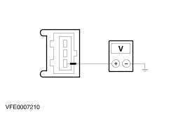
| | 4 Vehicles built before 08/2005, measure voltage between: - Vehicles without trailer socket: left-hand rear lamp assembly, connector C333, pin 2, circuit 15S-LG14 (GN/RD), wiring harness side and ground.
- Vehicles with trailer socket, vehicles built before 03/2004: left-hand rear lamp assembly, connector C333a, pin 2, circuit (BK/RD), wiring harness side and ground.
- Vehicles with trailer socket, vehicles built after 03/2004: left-hand rear lamp assembly, connector C333a, pin 2, circuit (GN), wiring harness side and ground.
|
| | 5 Vehicles built after 08/2005, measure voltage between: - Vehicles without trailer socket: left-hand rear lamp assembly, connector C333, pin 3, circuit 15S-LG14 (GN/RD), wiring harness side and ground.
- Vehicles with trailer socket: left-hand rear lamp assembly, connector C333a, pin 3, circuit (GN), wiring harness side and ground.
|
| | Does the meter display battery voltage? Yes Check and if necessary RENEW the left-hand rear lamp assembly. CHECK the operation of the system. No LOCATE and RECTIFY the break in the circuit(s) between soldered connection S12 and the left-hand rear lamp assembly using the Wiring Diagrams. CHECK the operation of the system. |
| B4: CHECK THE GROUND CONNECTION OF THE LEFT-HAND REAR LAMP ASSEMBLY |
| | 1 Ignition switch in position 0. |
| | 2 Disconnect Left-hand rear lamp assembly. - Vehicles without trailer socket: from connector C333
- Vehicles with trailer socket: from connector C333a
|
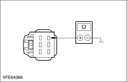
| | 3 Measure the resistance between the left-hand rear lamp assembly, vehicles built before 08/2005: - Vehicles without trailer socket: Connector C333, pin 4, circuit 31-LF23 (BK), wiring harness side and ground.
- Vehicles with 13-pin trailer socket, vehicles built after 03/2004: Connector C333a, pin 4, circuit (BN), wiring harness side and ground.
- All other vehicles with trailer socket: connector C333a, pin 4, circuit (GN), wiring harness side and ground.
|
| | 4 Measure the resistance between the left-hand rear lamp assembly, vehicles built after 08/2005: - Vehicles without trailer socket: connector C333, pin 4, circuit 31-LF23 (BK), wiring harness side and ground.
- Vehicles with 13-pin trailer socket: connector C333a, pin 4, circuit (BN), wiring harness side and ground.
- All other vehicles with trailer socket: connector C333a, pin 4, circuit (GN), wiring harness side and ground.
|
| | Is a resistance of less than 2 ohms registered? Yes CHECK and if necessary RENEW the left-hand rear lamp assembly. CHECK the operation of the system. No LOCATE and RECTIFY the break in the circuit(s) between the left-hand rear lamp assembly and soldered connection S24 using the Wiring Diagrams. CHECK the operation of the system. |
| B5: DETERMINE THE FAULT CONDITION |
| | 1 SWITCH ON parking lamps. |
| | 2 CHECK right-hand rear parking lamp. |
| | Does the right-hand rear parking lamp illuminate? Yes No |
| B6: CHECK THE VOLTAGE SUPPLY TO THE RIGHT-HAND STOP LAMP |
NOTE:The jumper wire used in the first step is still connected. |
| | 1 Ignition switch in position 0. |
| | 2 Disconnect Right-hand rear lamp assembly. - Vehicles without trailer socket: from connector C348
- Vehicles with trailer socket: from connector C348a
|
| | 3 Ignition switch in position II. |
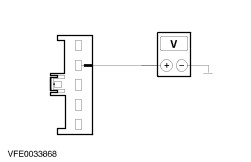
| | 4 Vehicles built before 08/2005, measure voltage between: - Vehicles without trailer socket: right-hand rear lamp assembly, connector C348, pin 2, circuit 15S-LG21 (GN/BK), wiring harness side and ground.
- Vehicles with trailer socket, built before 03/2004: right-hand rear lamp assembly, connector C348a, pin 2, circuit (GN), wiring harness side and ground.
- Vehicles with trailer socket, built after 03/2004: right-hand rear lamp assembly, connector C348a, pin 2, circuit (BK/RD), wiring harness side and ground.
|
| | 5 Vehicles built after 08/2005, measure voltage between: - Vehicles without trailer socket: right-hand rear lamp assembly, connector C348, pin 3, circuit 15S-LG21 (GN/BK), wiring harness side and ground.
- Vehicles with trailer socket: right-hand rear lamp assembly, connector C348a, pin 3, circuit (BK/RD), wiring harness side and ground.
|
| | Does the meter display battery voltage? Yes CHECK and if necessary RENEW the right-hand rear lamp assembly. CHECK the operation of the system. No LOCATE and RECTIFY the break in the circuit(s) between soldered connection S12 and the right-hand rear lamp assembly using the Wiring Diagrams. CHECK the operation of the system. |
| B7: CHECK THE GROUND CONNECTION TO THE RIGHT-HAND REAR LAMP ASSEMBLY |
| | 1 Ignition switch in position 0. |
| | 2 Disconnect Right-hand rear lamp assembly. - Vehicles without trailer socket: from connector C348
- Vehicles with trailer socket: from connector C348a
|
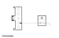
| | 3 Measure the resistance between the right-hand rear lamp assembly, vehicles built before 08/2005: - Vehicles without trailer socket: connector C348, pin 4, circuit 31-LF24 (BK), wiring harness side and ground.
- Vehicles with trailer socket, built before 03/2004: connector C348a, pin 4, circuit (BK), wiring harness side and ground.
- Vehicles with trailer socket, built after 03/2004: connector C348a, pin 4, circuit (BN), wiring harness side and ground.
|
| | 4 Measure the resistance between the right-hand rear lamp assembly, vehicles built after 08/2005: - Vehicles without trailer socket: connector C348, pin 4, circuit 31-LF24 (BK), wiring harness side and ground.
- Vehicles with trailer socket: connector C348a, pin 4, circuit (BN), wiring harness side and ground.
|
| | Is a resistance of less than 2 ohms registered? Yes CHECK and if necessary RENEW the right-hand rear lamp assembly. CHECK the operation of the system. No LOCATE and RECTIFY the break in the circuit(s) between the right-hand rear lamp assembly and ground connection G18 using the Wiring Diagrams. CHECK the operation of the system. |
| B8: CHECK THE VOLTAGE TO THE ADDITIONAL HIGH-MOUNTED STOP LAMP |
NOTE:The jumper wire used in the first step is still connected. |
| | 1 Ignition switch in position 0. |
| | 2 Disconnect Additional high-mounted stop lamp from connector C550. |
| | 3 Ignition switch in position II. |
| | 4 Measure the voltage between the additional high-mounted stop lamp, connector C550, pin 1: - Vehicles without anti-theft alarm system: circuit 15S-LG6 (GN/YE), wiring harness side and ground.
- Vehicles with anti-theft alarm system: circuit 31-LG6S (BK), wiring harness side and ground.
|
| | Does the meter display battery voltage? Yes No LOCATE and RECTIFY the break in the circuit(s) between soldered connection S12 and the additional high-mounted stop lamp using the Wiring Diagrams. CHECK the operation of the system. |
| B9: CHECK GROUND CONNECTION OF ADDITIONAL HIGH-MOUNTED STOP LAMP |
| | 1 Ignition switch in position 0. |
| | 2 Measure the resistance between the additional high-mounted stop lamp, connector C550, pin 2, circuit 31-LG6 (BK), wiring harness side and ground. |
| | Is a resistance of less than 2 ohms registered? Yes CHECK and if necessary RENEW the additional high-mounted stop lamp. CHECK the operation of the system. No LOCATE and RECTIFY the break in the circuit between the additional high-mounted stop lamp and soldered connection S201 using the Wiring Diagrams. CHECK the operation of the system. |