
Fusion AWD L4-2.3L (2008)
16. NOTE: It is necessary to connect the electrical connectors in the same positions as noted in disassembly. Connector color letters are cast into the
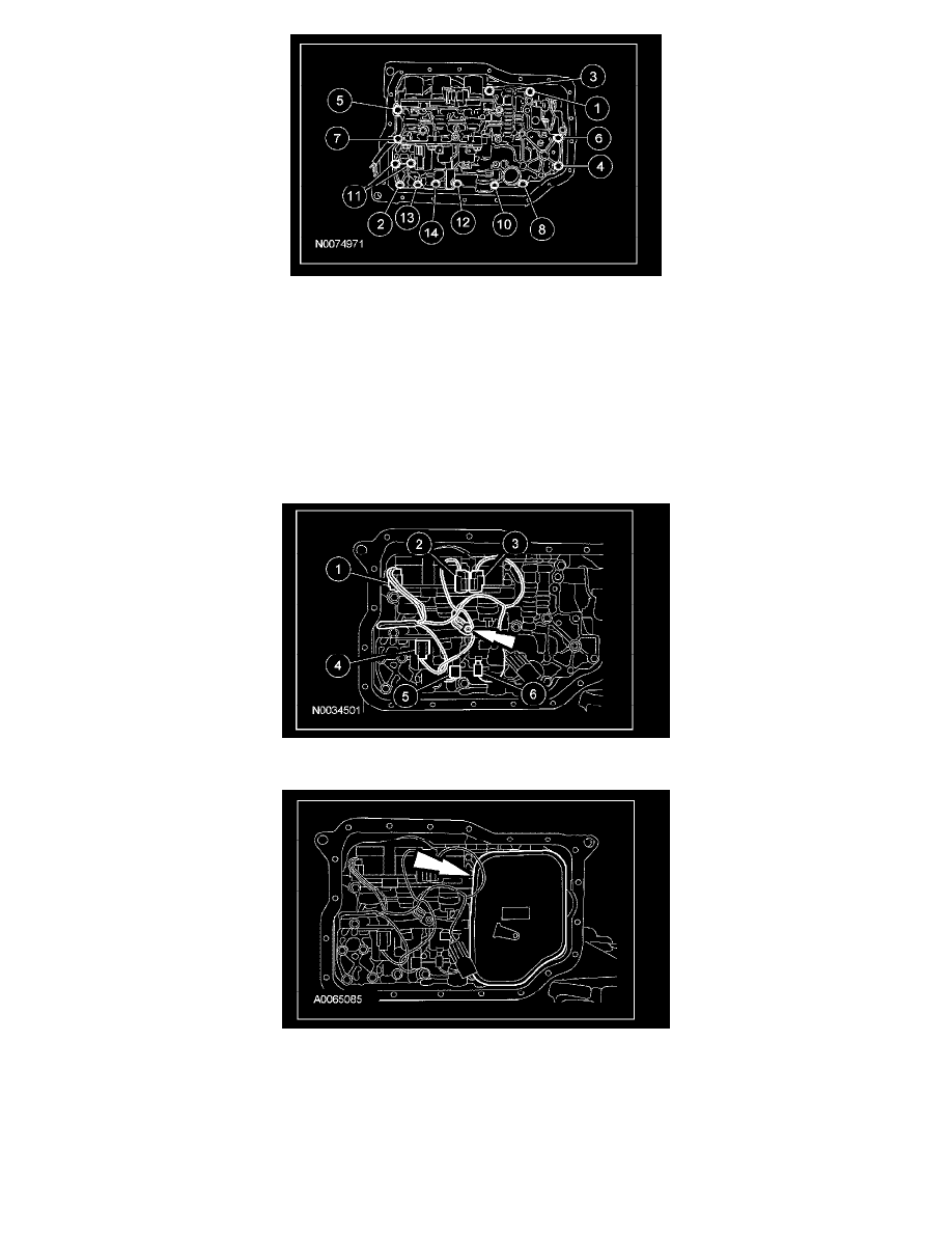
solenoid body.
Install the main control valve wiring harness, connect the electrical connectors and install the ground wire bolt.
1
Solenoid SSA, color (BU/GN).
2
Solenoid SSB, color (BK/GN).
3
Solenoid SSC, color (BU/BN).
4
Solenoid PCA, color (BU/BN).
5
Solenoid SSD, color (WH).
6
Solenoid SSE, color (RD).
^
Tighten to 10 Nm (89 lb-in).
17. Install the transmission fluid filter.
18. Connect the TFT sensor electrical connector.