
Fusion FWD V6-30L (2009) Powertrain Management - Component Information Testing | Page 2997
-
Ignition OFF.
-
Disconnect: Negative Battery Cable.
-
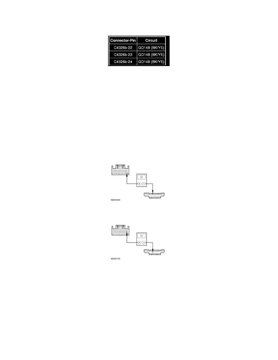
Measure the resistance between the audio DSP module amplifier, harness side and ground as follows:
-
Are the resistances less than 5 ohms?
Yes
GO to L3.
No
REPAIR the circuit. CONNECT the negative battery cable. CLEAR the DTCs. REPEAT the network test with the scan tool.
-------------------------------------------------
L3 CHECK THE MS-CAN CIRCUITS BETWEEN THE AUDIO DSP MODULE AND THE DLC FOR AN OPEN
-
Ignition OFF.
-
Disconnect: Audio DSP Module C4326c.
-
Measure the resistance between the audio DSP module C4326c-11, circuit VDB06 (GY/OG), harness side and the Data Link Connector (DLC)
C251-3, circuit VDB06 (GY/OG), harness side.
-
Measure the resistance between the audio DSP module C4326c-1, circuit VDB07 (VT/OG), harness side and the DLC C251-11, circuit VDB07
(VT/OG), harness side.
-
Are the resistances less than 5 ohms?
Yes
CONNECT the negative battery cable. GO to L4.
No
REPAIR the circuit in question. CONNECT the negative battery cable. CLEAR the DTCs. REPEAT the network test with the scan tool.
-------------------------------------------------
L4 CHECK FOR CORRECT AUDIO DSP MODULE OPERATION
-
Disconnect all the audio DSP module connectors.
-
Check for:
-
corrosion