
Fusion FWD V6-3.0L (2009)
No
REPAIR the circuit in question. CONNECT the negative battery cable. CONNECT the SJB. CLEAR the DTCs. REPEAT the network test with the scan
tool.
-------------------------------------------------
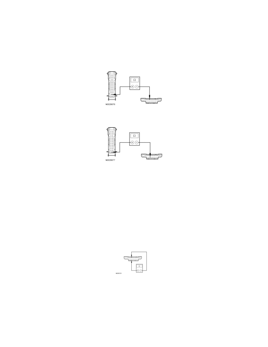
R8 CHECK THE MS-CAN CIRCUITS BETWEEN THE IC AND THE DLC FOR AN OPEN
-
Measure the resistance between the Instrument Cluster (IC) C220-2, circuit VDB06 (GY/OG), harness side and the DLC C251-3, circuit VDB06
(GY/OG), harness side.
-
Measure the resistance between the IC C220-1, circuit VDB07 (VT/OG), harness side and the DLC C251-11, circuit VDB07 (VT/OG), harness
side.
-
Are the resistances less than 5 ohms?
Yes
VERIFY all module fuses are OK. If OK, CONNECT all modules. CONNECT the negative battery cable. REPEAT the network test with the scan tool.
No
REPAIR the circuit in question. CONNECT the negative battery cable. CLEAR the DTCs. REPEAT the network test with the scan tool.
-------------------------------------------------
R9 CHECK THE MS-CAN (+) AND MS-CAN (-) CIRCUITS FOR A SHORT TOGETHER WITH THE SJB DISCONNECTED
-
Disconnect: SJB C2280d.
-
Measure the resistance between the DLC C251-3, circuit VDB06 (GY/OG), harness side and the DLC C251-11, circuit VDB07 (VT/OG), harness
side.
-
Is the resistance less than 5 ohms?
Yes
GO to R10.
No
CONNECT the negative battery cable. GO to R47.
-------------------------------------------------